Detailed Guide to Choosing a Line Boring Machine
What to Know Before Choosing a Line Boring Machine
A line boring machine is a precision machining tool used to restore, enlarge, or realign existing bores in heavy industrial equipment, including gearbox housings, excavator pivots, crane frames, and conveyor drive components. When a bore wears out of round or loses its concentricity, line boring is often the fastest and most cost-effective fix available without replacing the entire component.
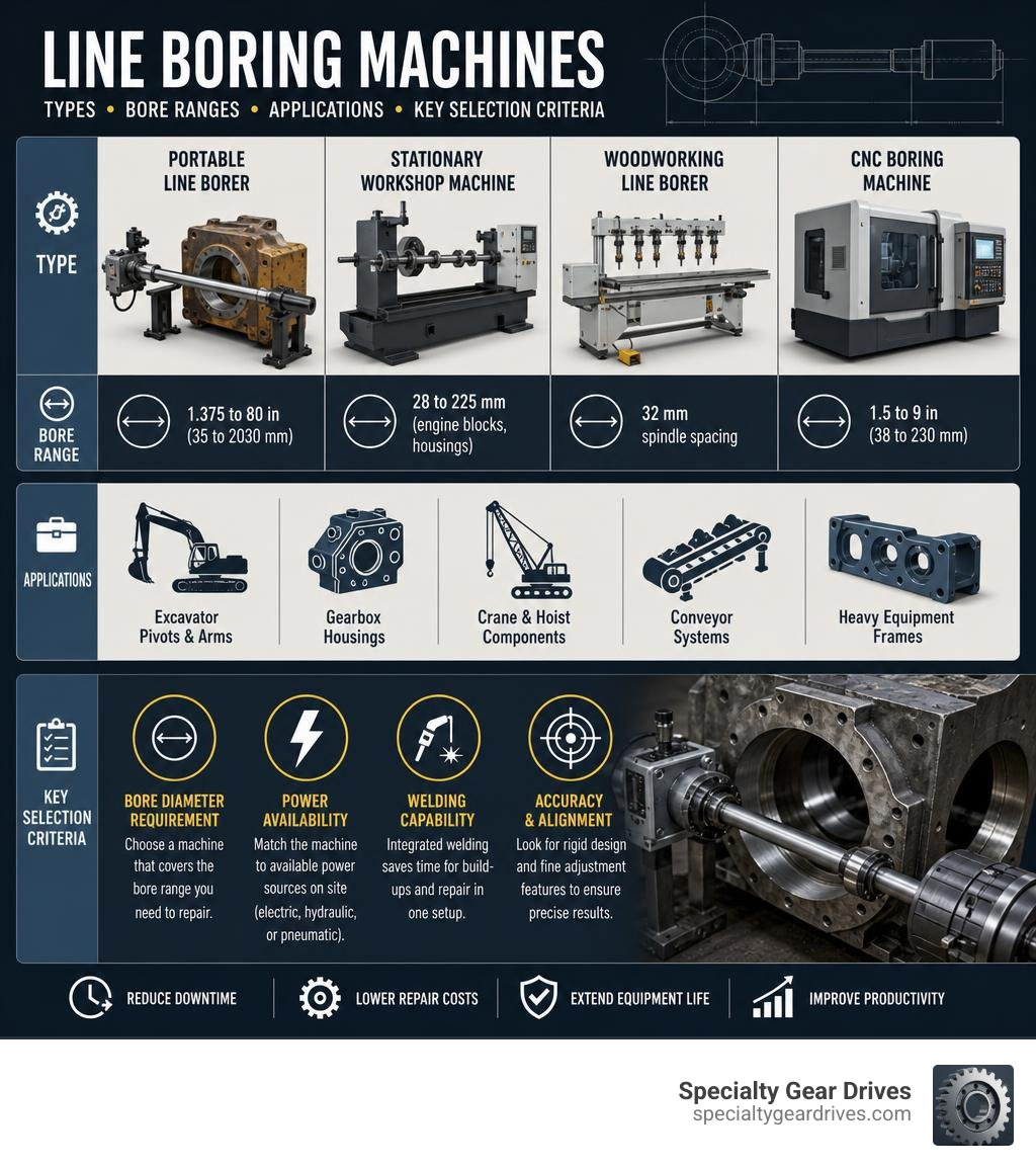
Here is a quick breakdown of what line boring machines are used for and what types exist:
| Type | Best For | Typical Bore Range |
|---|---|---|
| Portable line borer | On-site repair of heavy equipment | 1.375 to 80 inches (35 to 2030 mm) |
| Stationary workshop machine | High-volume shop reconditioning | 28 mm to 225 mm (engine blocks, housings) |
| Woodworking line borer | Multi-spindle cabinet and furniture drilling | 32 mm spindle spacing |
| CNC boring machine | Automated, high-precision production boring | 1.5 to 9 inches (38 to 230 mm) |
For plant maintenance teams in heavy industry, the portable type is usually the one that matters most. A worn gearbox housing bore does not need to travel to a machine shop if the right equipment can be brought directly to your facility. That alone can cut days or weeks off a repair timeline.
The core decision when selecting a line boring machine comes down to three things: the bore diameter you need to repair, the available power source on site, and whether you need welding capability integrated into the same setup.
The sections below cover each factor in detail, including bar sizes, tooling choices, repair methods, and how to verify accuracy after the cut.
Learn more about line boring machine:
What is a Line Boring Machine and How Does It Work?
A line boring machine works by rotating a cutting tool inside an existing bore while feeding it along the axis of the hole. This mechanical chip-removal process enlarges the internal diameter, corrects out-of-roundness, and ensures multiple collinear bores are perfectly aligned on the same centerline. It is the primary method for reclaiming worn-out bearing seats, hinge pin holes, and coupling alignments in heavy machinery.
When industrial gearboxes operate under high torque load, the constant radial forces can cause the bearing bores in the housing to stretch or become egg-shaped. This wear introduces shaft misalignment, which quickly destroys new bearings and ruins gear tooth contact patterns. Line boring cuts away the damaged metal, restoring the bore to its original circular geometry and alignment.
To understand how this process applies specifically to industrial housings and gear reducers, you can read The Complete Guide to Line Boring Housing Machining.
Core Components of a Portable Line Boring Machine
The performance of a portable line boring system relies on several modular components working together to maintain rigidity. Because the machine must operate in the field, these parts are designed to be clamped directly onto the machinery being repaired.
- Boring Bar: The central shaft that holds the cutting tool. High-quality bars are made of chrome-plated, induction-hardened alloy steel with a tensile strength of around 100,000 PSI to resist bending under heavy cutting forces. Hard chrome plating prevents scratches and stops weld splatter from sticking.
- Spherical Bearings: These support the boring bar on either side of the workpiece. Spherical bearings are self-aligning, allowing up to 5 degrees of misalignment during setup without binding the bar.
- Mounting Brackets and Standoffs: These plates weld or bolt directly to the gearbox housing or machine frame to hold the bearings securely in place.
- Centering Cones: Tapered aluminum or cast-iron cones that slide onto the bar and fit into the worn bores to quickly establish the initial centerline before the mounting brackets are welded down.
- Rotational Drive and Feed Unit: The motor and gearbox assembly that rotates the bar and feeds the tool carrier smoothly along the length of the bore.
Portable vs. Stationary Line Boring Machine Systems
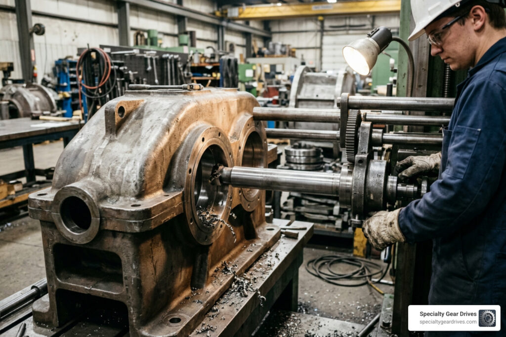
Portable systems are designed to bring the machine shop directly to the job site. The workpiece remains completely fixed, and the portable unit is mounted directly to it. This setup is ideal for large, heavy castings like industrial gearboxes, where disassembly and transport costs would be prohibitive.
Stationary workshop machines, such as large horizontal boring mills, require the damaged component to be fully stripped down, loaded onto a truck, and clamped to a massive machine table. While stationary machines offer maximum rigidity and are excellent for manufacturing new parts, they introduce massive logistics bottlenecks and extended downtime for emergency field repairs.
| Feature | Portable Line Boring Systems | Stationary Workshop Mills |
|---|---|---|
| Workpiece Status | Fixed in place on the plant floor | Disassembled and transported to shop |
| Setup Location | Directly on the industrial machinery | Secured to a heavy machine table |
| Typical Lead Time | Hours to days | Weeks |
| Rigidity | High (when properly braced) | Extremely high |
| Best For | Emergency repairs and heavy field maintenance | New manufacturing and complete rebuilds |
Key Specifications for Selecting a Line Boring Machine
Selecting the right machine requires matching the equipment specifications to the physical dimensions and material hardness of the workpiece.
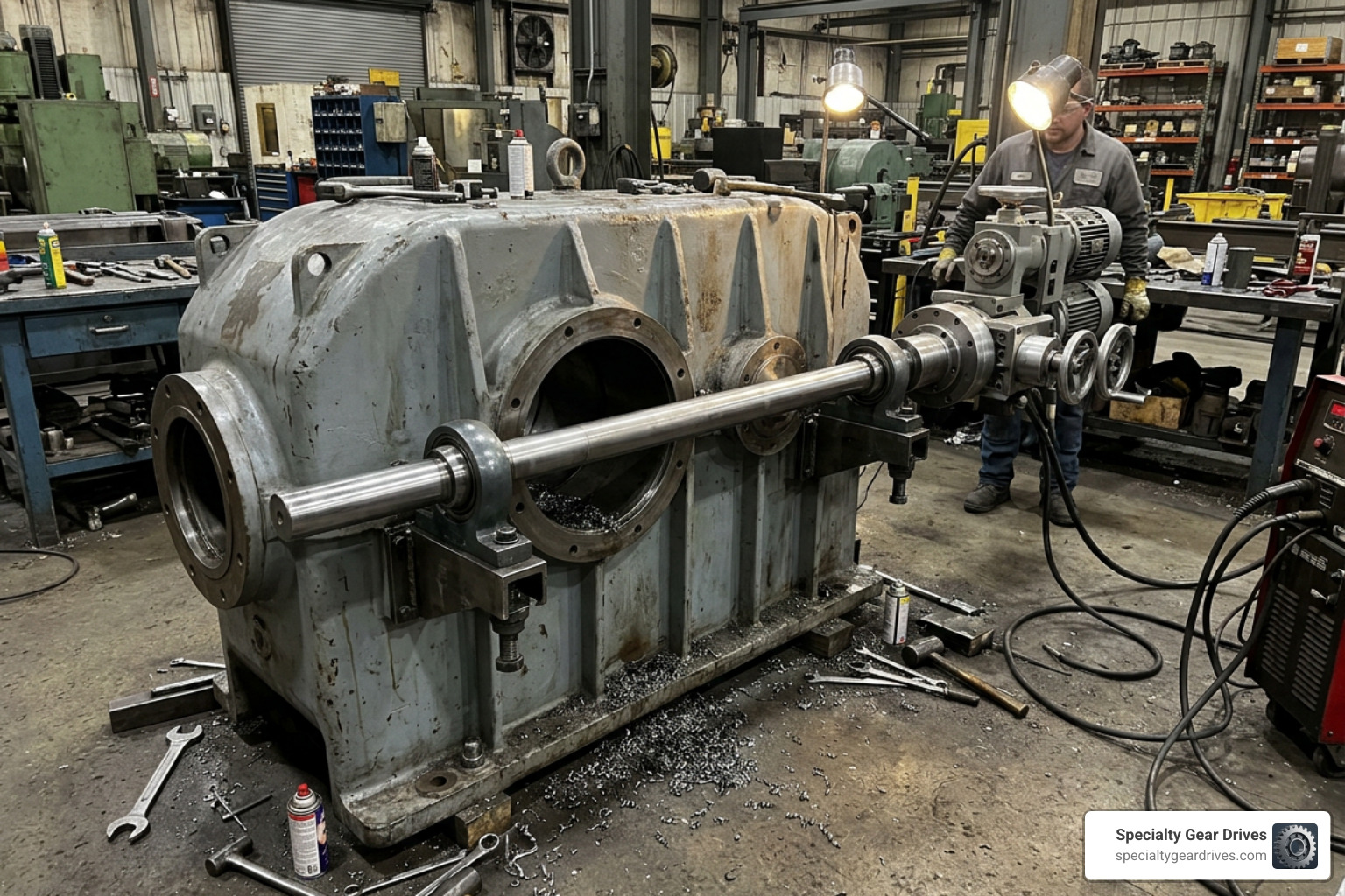
The first specification to check is the bar diameter. A bar that is too small for the bore length will deflect under the pressure of the cut, resulting in a tapered or out-of-round hole.
The torque rating of the drive unit is another critical factor. Cutting through tough materials like cast steel or hardened weld overlays requires low rotational speeds paired with high torque. If the motor lacks sufficient torque, the cutter will stall, causing tool breakage and poor surface finishes.
Power options for the drive unit generally include electric, pneumatic, and hydraulic systems. Electric motors are highly portable and convenient for standard indoor plant environments. Pneumatic drives are preferred in spark-free zones, such as petrochemical plants. Hydraulic power units deliver the highest torque-to-weight ratio, making them the industry standard for large-diameter boring where heavy metal removal is required.
Boring Diameter Ranges and Bar Sizes
To prevent bar deflection, the rule of thumb is to use the largest bar diameter that will fit within the bore while still leaving room for the cutting tool and tool holder. Portable line boring machines support a wide range of boring diameters, typically from 1.375 to 80 inches (35 to 2030 mm).
For smaller jobs, a compact machine like the BB3000 uses a 1.25-inch (31.8 mm) bar to handle boring diameters from 1.5 to 5 inches (38 to 127 mm). These are ideal for tight spaces and smaller bearing pockets on conveyor drives.
Mid-range workhorses, such as the BB5000, utilize a 2.25-inch (57.2 mm) bar to cover boring diameters from 1.5 to 24 inches (38.1 to 609.6 mm). For massive industrial gearboxes, heavy mining equipment, and large-diameter shafts, heavy-duty machines like the BB8100 feature an 8-inch (203.2 mm) bar and can bore diameters up to 85.6 inches (2174.2 mm).
You can find more detailed information on matching bar sizes to specific rebuild projects in The Ultimate Guide to Line Boring Rebuild Services.
Tooling and Cutting Materials
The choice of cutting tool material directly impacts the surface finish and dimensional accuracy of the finished bore.
- Carbide Inserts: Indexable carbide inserts are the industry standard for most line boring applications. They offer high hardness, excellent wear resistance, and can handle the high temperatures generated during dry cutting.
- Cobalt Steel: High-speed cobalt steel tool bits are tougher and less brittle than carbide. They are often used for interrupted cuts or when machining highly irregular, out-of-round bores where carbide might chip.
- Insert Tooling Geometry: Square or triangular indexable inserts allow operators to quickly rotate the insert to a fresh cutting edge without removing the tool holder, maintaining setup alignment.
When setting cutting speeds and feed rates, operators must balance the material hardness with the bore diameter. Large diameters require lower rotational speeds (RPM) to keep the surface speed of the cutting edge within the recommended limits for the tool material. Depth of cut should be kept light on the final pass to minimize tool deflection and achieve a smooth surface finish.
Step-by-Step Setup and Bore Repair Methods
Achieving near-zero Total Indicator Runout (TIR) requires patience and a systematic approach to the setup process.
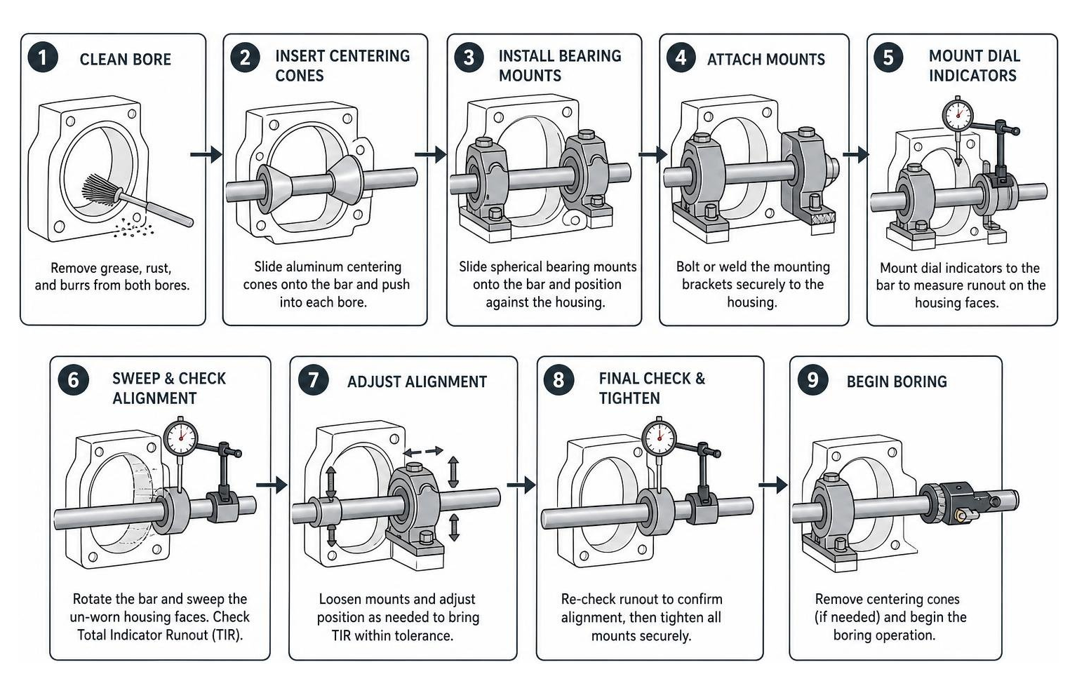
The alignment process begins by cleaning the worn bore to remove grease, rust, and burrs. Aluminum centering cones are then slipped onto the boring bar and pushed into the bores on either side. These cones temporarily center the bar relative to the original machined surfaces.
Once the bar is centered, spherical bearing mounts are slid onto the bar and positioned against the gearbox housing. The mounting brackets are then welded or bolted to the housing. To ensure the alignment is perfect, operators use dial indicators mounted to the bar, sweeping the original un-worn faces of the housing to verify concentricity before tightening the bearings.
For a deeper look at how this on-site process saves heavy machinery from the scrap heap, read Bore No More How Housing Line Boring Repairs Heavy Equipment.
Weld and Rebore vs. Oversize Sleeves
When a bore is worn beyond its design limits, simply cutting it larger is often not an option because it would alter the standard bearing outer diameter. There are two primary ways to restore the bore to its original factory dimensions.
The first method is the weld and rebore process. An automatic bore welder is mounted to the same setup as the line boring machine. The welder applies a uniform layer of new steel to the inside of the worn bore. Once cooled, the line boring machine cuts the new weld metal back to the exact original specification. This creates a seamless, full-strength repair.
The second method involves machining the worn bore oversize and pressing in a custom-machined sleeve or bushing. This is often faster than welding, but it requires sufficient wall thickness in the housing casting to accept the larger outside diameter of the sleeve without weakening the structure.
To understand how welding restores structural integrity to damaged castings before machining begins, refer to How Gearbox Housing Welding Services Restore Damaged Castings.
Measuring and Verifying Bore Accuracy
Precision measurement must happen throughout the boring process, not just at the end.
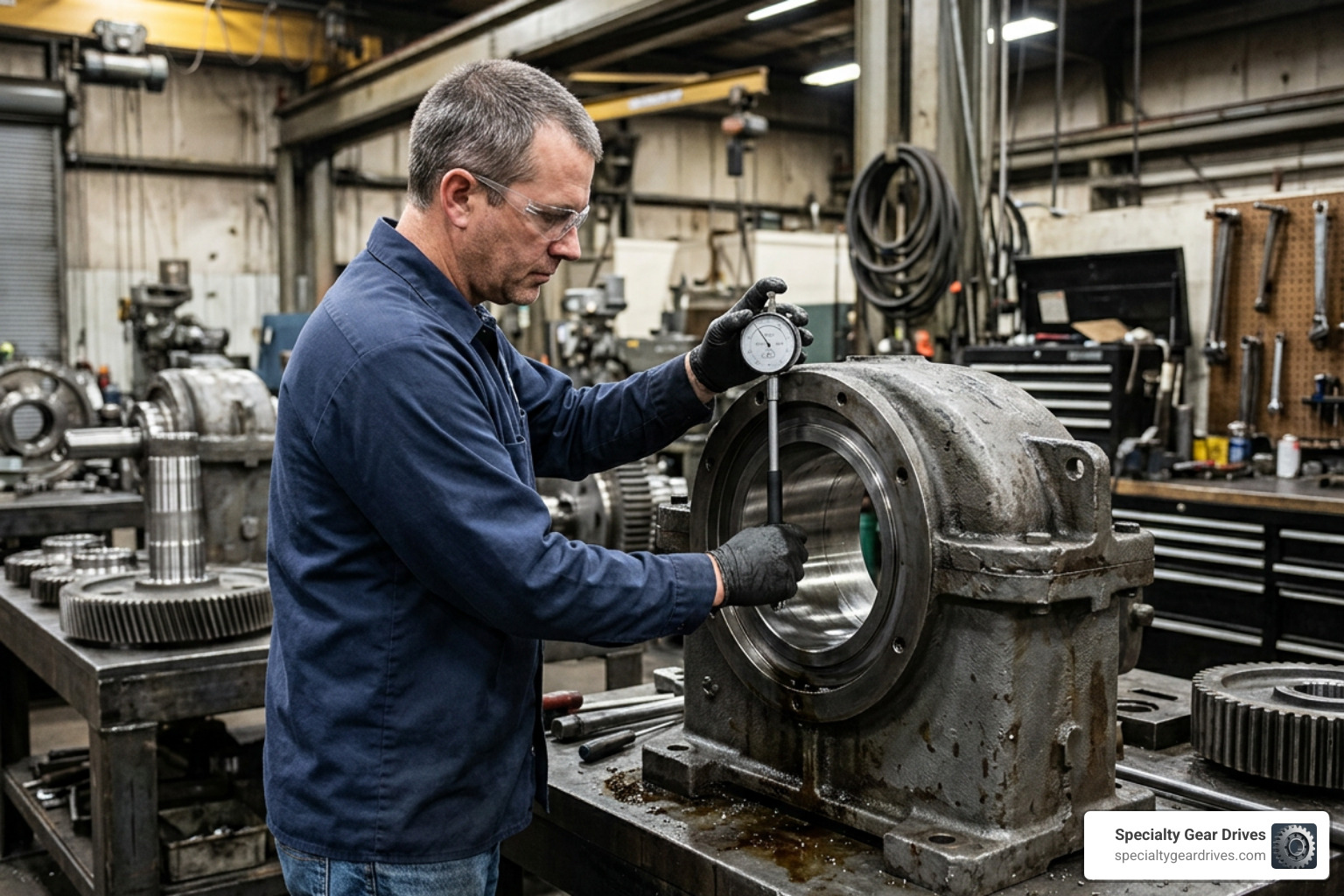
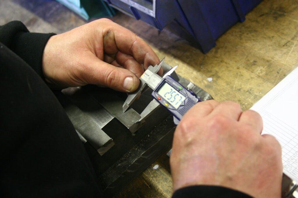
Before the final pass, the operator must measure the bore diameter to determine exactly how much material remains to be removed. Standard inside calipers or telescoping bore gauges are used for quick checks.
For high-precision industrial bearing fits, a dial bore gauge or micrometer is required. These tools measure down to 0.001 inches (0.025 mm) or better, ensuring the finished hole meets the precise interference or clearance fit specified by the bearing manufacturer. Digital positioners and electronic travel indicators can also be mounted to the feed unit to track the axial movement of the cutter in real time.
Overcoming Common Line Boring Challenges
One of the most common issues during a line boring operation is cutter chatter. This is a high-frequency vibration that leaves a wavy pattern on the machined surface and ruins the cutting edge. Chatter is usually caused by lack of rigidity. It can be mitigated by shortening the distance between the support bearings, reducing the cutter extension, or slowing down the spindle speed while increasing the feed rate.
Another major challenge is weld hardness. When automatic bore welders are used on cast iron or high-carbon steel housings, rapid cooling can create hard spots or chilled zones in the weld metal. When the cutting tool hits these hard spots, it can deflect, chip, or dull instantly. Pre-heating the casting before welding and using specialized carbide grades designed for hardened materials can help prevent tool damage.
If you are facing a complex alignment or severe housing damage, it is often best to consult with specialists. You can find professional help by visiting Line Boring Gearbox Housing Find Professional Services.
Frequently Asked Questions about Line Boring
How does line boring compare to honing or using a magnetic drill press alone?
Line boring is designed to correct alignment and concentricity errors across long distances or multiple bores. Honing is a finishing process that uses abrasive stones to improve surface finish and make micro-adjustments to the bore diameter, but it cannot correct a hole that is out of alignment.
A magnetic drill press is designed for drilling new holes in flat plate. It lacks the long-distance support bearings and structural rigidity needed to bore deep, precise cylinders. While some modular kits allow you to use a magnetic drill press as the rotational drive motor for a line boring bar, you must use a specialized adapter base with a built-in load-bearing design to protect the drill’s internal bearings from the radial forces of the cutting action.
What safety precautions are critical during line boring operations?
Operating a line boring machine involves high-torque rotating shafts and sharp cutting tools. Operators must ensure the rotational drive has an automatic stop or emergency shut-off switch within reach at all times.
Because the machine is often mounted to vertical or overhead surfaces, all mounting brackets must be welded or bolted securely to prevent the assembly from falling. If using a magnetic drill press drive, a safety chain or strap must secure the drill base to the workpiece in case of a sudden power failure.
What accessories can upgrade a standard line boring setup?
- Servo Motor Kits: Upgrading from standard electric motors to AC servo motors provides constant torque across the entire speed range and allows for precise digital speed control.
- Facing Heads: These attachments mount directly to the boring bar, allowing the operator to machine the flat end faces of the housing or flange in the same setup, ensuring the face is perfectly perpendicular to the bore axis.
- Digital Readouts (DRO): DRO systems track the precise position of the cutting tool along the bar, eliminating manual measurement errors during blind-hole boring.
Conclusion
Choosing the right line boring machine or service provider is critical for minimizing downtime and ensuring the long-term reliability of your industrial rotating equipment. Whether you are dealing with a worn bearing pocket on a conveyor drive or a misaligned shaft bore on a massive speed reducer, precision is the only thing that stands between a successful repair and another catastrophic failure.
At Specialty Gear Drives, we specialize in the repair and rebuilding of heavy-duty industrial gearboxes. Operating out of our state-of-the-art facility in Largo, Florida, we provide rapid-response services to industrial facilities across the Southeast, including Florida, Georgia, Alabama, South Carolina, Mississippi, and Louisiana. We understand the unique demands of regional industries, from pulp and paper mills in Alabama and Mississippi to phosphate mining operations in Florida and petrochemical plants along the Louisiana coast.
Our key advantages include:
- 24–48 Hour Emergency Service: We get your critical lines back up and running fast.
- Free Pickup and Delivery: We handle the logistics so your team can focus on the plant.
- Up to 60% Savings: Rebuilding your housing and gears with us saves a significant portion of the cost of buying new.
- 24-Month Warranty: We stand behind our work with an industry-leading warranty.
If your plant is dealing with worn gearbox housings or shaft alignment issues, contact us today to discuss how we can restore your machinery to factory specifications. Learn more about our full capabilities by visiting our Industrial Gearbox Repair service page.