What a 60:1 Gear Reducer Does in Practical Terms
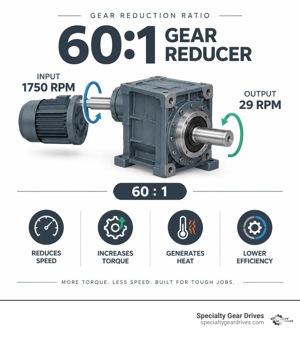
A 60:1 gear reducer turns the output shaft once for every 60 turns of the input shaft. With a typical 1,750 RPM motor, it produces about 29 RPM at the output. It reduces speed and increases available output torque, but worm-drive friction also creates heat and reduces efficiency.
Before specifying a reducer, confirm these basics:
- Input motor speed and horsepower
- Required output RPM and running torque
- Service factor for shock loads or long duty cycles
- Thermal rating for continuous operation
- Mounting, output bore, overhung load, and thrust load requirements
For example, a 60:1 aluminum right-angle worm reducer with a NEMA 56C input flange can suit compact conveyors, mixers, and material-handling equipment. A cast-iron model may be a better fit where higher rigidity, vibration damping, and demanding industrial duty matter most.
I am Peter Clark, owner of Specialty Gear Drives in Largo, Florida, where I oversee in-house repair, reverse engineering, and rebuilding of industrial worm, helical, and bevel gearboxes. My experience with 60 1 gear reducer failures and rebuilds helps plants across the Southeast match ratio, load capacity, heat limits, and configuration to the actual job.
Must-know 60 1 gear reducer terms:
Fundamentals and Physics of 60:1 Gear Reduction
A 60:1 reduction ratio provides massive mechanical advantage in a compact footprint by converting high-speed, low-torque motor rotation into low-speed, high-torque driving power. Achieving this substantial reduction in a single stage is a distinct mechanical property of worm gearing, where a single-start or double-start hardened steel worm meshes directly with a bronze gear wheel. To explore these mechanics in greater depth, review our worm gear speed reducer fundamentals.
The trade-off for this high ratio is mechanical efficiency. Because the teeth slide against each other rather than rolling, friction takes a bite out of total power transfer, generating heat that must be accounted for during sizing.
Speed Reduction and Torque Multiplication Dynamics
A 60:1 drive drops a standard 1,750 RPM induction motor speed down to roughly 29.1 RPM. To determine the theoretical output torque before efficiency losses, multiply the input motor torque by the 60:1 ratio.
The gear lead angle on a 60:1 single-reduction set is relatively shallow, which increases torque multiplication while introducing high sliding friction across the tooth contact pattern.
Efficiency Losses and Heat Generation in Worm Drives
Worm drives operating at a 60:1 ratio typically yield mechanical efficiencies between 70% and 80%, meaning 20% to 30% of input power turns directly into thermal energy. A hardened alloy steel worm running against a phosphor bronze gear generates significant sliding friction, demanding consistent oil film strength to prevent direct metal contact.
For plants seeking higher mechanical efficiency above 95%, alternative options such as inline drive configurations provide an effective multi-stage helical arrangement, though they require a larger physical envelope.
Selecting the Right 60 1 Gear Reducer for Heavy Industry
Properly sizing a drive requires balancing mechanical capacity, thermal dissipation limits, and operational duty cycles. Selecting a 60 1 gear reducer under AGMA standards ensures the unit tolerates operational shock loads without stripping bronze gear teeth or fatiguing shaft bearings. For comprehensive sizing rules and service factor charts, refer to our comprehensive gear reducer guide.
Matching the electric motor horsepower directly to the gearbox capacity prevents premature burnout. Operating a heavily loaded conveyor across continuous 24-hour shifts in hot southern facilities demands a higher service factor than intermittent material handling.

Mechanical vs. Thermal Ratings for a 60 1 Gear Reducer
Mechanical torque measures the physical shear strength of gear teeth, shafts, and housing components under load. Thermal horsepower represents the maximum continuous power the unit can transmit before the oil sump temperature exceeds safe limits, typically 200 degrees Fahrenheit.
In a high-ratio worm drive, the thermal rating is frequently lower than the mechanical rating during continuous duty. When a gearbox runs continuously without auxiliary cooling, heat builds faster than the housing can shed it to ambient air, leading to oil breakdown and rapid gear failure.
Aluminum vs. Cast Iron 60 1 Gear Reducer Construction
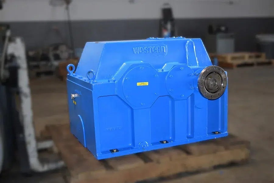
Choosing between an aluminum alloy housing and heavy cast iron depends on environmental conditions, weight constraints, and structural load requirements. Aluminum offers superior heat transfer and lighter weight for modular equipment, while cast iron delivers maximum rigidity, vibration dampening, and resistance to severe structural shock loads.
| Characteristic | Aluminum Housing (e.g., 90 mm Center Distance) | Cast Iron Housing (e.g., 2.375″ Center Distance) |
|---|---|---|
| Typical Unit Weight | Approx. 28 lbs | Approx. 40 lbs |
| Heat Dissipation | Higher natural thermal conductivity | Slower heat dissipation |
| Structural Rigidity | Moderate; suitable for packaged machinery | High; resists heavy shock and housing deflection |
| Vibration Damping | Standard | Superior natural dampening |
| Corrosion Protection | Epoxy-painted aluminum alloy | Painted heavy-wall cast iron |
| Typical Max Torque | Up to 2,960 in-lb (depending on size) | 1,418 in-lb (at standard center distance) |
| Overhung Load Limit | Moderate radial capacity | High radial capacity (e.g., 843+ lbf) |
Configuration Options: Flanges, Mounts, and Shaft Layouts
Industrial gear reducers rely on versatile mounting systems to integrate cleanly with diverse machinery frames. Base mounting feet, bolt-on output flanges, and torque reaction arms allow engineers to position the drive horizontally, vertically, or directly suspended on driven machine shafts.
Accounting for overhung load and radial thrust capacity is essential when driving machinery through sprockets, pulleys, or direct rigid couplings.
NEMA 56C Flange Compatibility and Motor Integration
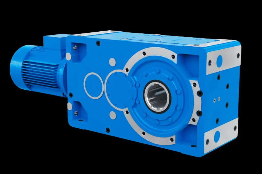
A NEMA 56C input flange provides direct, standardized quill-style mounting for fractional and low-horsepower industrial electric motors. This direct-coupled configuration eliminates alignment issues associated with external couplings and belt drives, securing the motor face square to the input worm shaft.
Most 60:1 reducers with a 56C face accept standard motors rated from 0.5 HP to 1.5 HP, ensuring proper mechanical balance without overloading the high-ratio worm assembly.
Hollow Bore vs. Solid Shaft Output Configurations
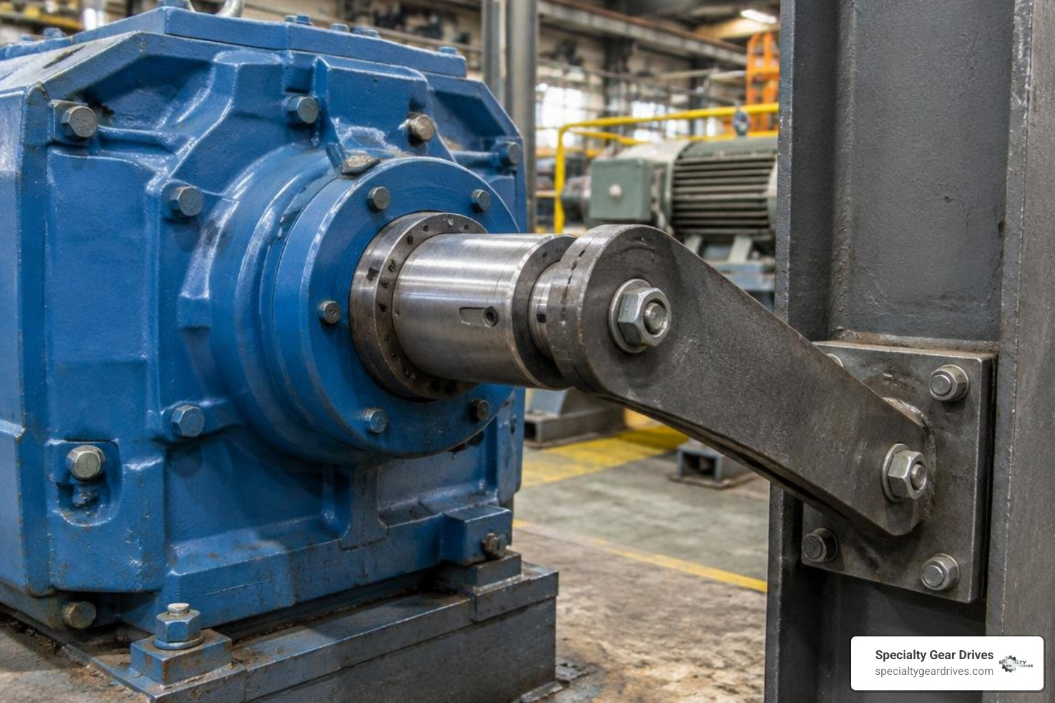
Hollow bore output shafts slide directly over the driven machine shaft, locked in place with a standard keyway and set screws. This shaft-mounted orientation eliminates flexible couplings, mounting bases, and alignment steps, significantly reducing machine footprint.
Solid output shafts (available in single-ended or double-ended layouts) remain the standard choice when delivering power through chain drives, heavy sprockets, or external bearing pillow blocks.
Industrial Applications, Maintenance, and Failure Prevention
Worm gear reducers power critical machinery across processing plants, quarries, and packaging facilities throughout Florida, Georgia, Alabama, South Carolina, Mississippi, and Louisiana. Maintaining these high-reduction drives requires strict attention to oil quality, operating temperatures, and seal integrity. Review our guide on preventable gearbox repair mistakes to protect your plant from unexpected downtime.
Heavy-Duty Use in Mining, Conveyors, and Processing
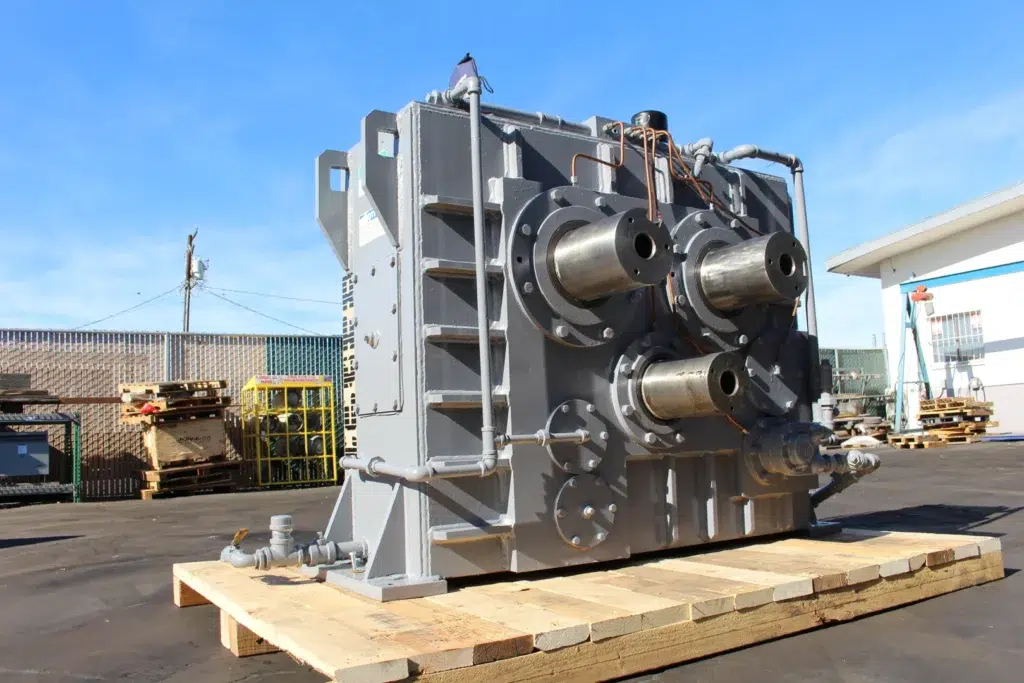
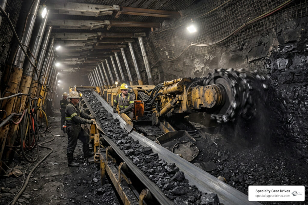
Severe industrial duty in aggregate mining, chemical processing, and bulk material handling exposes reducers to high shock loads and abrasive dust. High-ratio worm units drive slow-moving apron feeders, bucket elevators, wastewater aerators, and heavy mixing tanks where continuous torque and compact footprints are mandatory.
When standard commercial gearing cannot meet uncommon center distances or proprietary plant requirements, our team provides precision custom industrial gear manufacturing to replicate or upgrade worn components.
Lubrication Protocols and Seal Integrity Management
High sliding friction demands premium lubricants, typically ISO VG 460 synthetic polyglycol or heavy compounded mineral oils designed specifically for bronze worm gearing. Standard extreme-pressure oils containing active sulfur additives should be avoided because they chemically attack bronze gear teeth.
Double-lip Viton seals keep abrasive plant dust out while retaining oil. If bronze tooth wear debris accumulates in the oil sump, or bearing play develops, our complete gearbox rebuild process restores critical tolerances, replaces bearings, and resets proper backlash.
Frequently Asked Questions About 60:1 Speed Reducers
How do you calculate output speed and torque for a 60:1 reduction?
Divide the motor input speed by 60 to find the output RPM. For a 1,750 RPM motor, the calculation yields 29.16 RPM.
$$text{Output RPM} = frac{text{Input RPM}}{text{Ratio}} = frac{1750}{60} approx 29.17text{ RPM}$$
To calculate mechanical output torque, multiply input torque by 60 and multiply by the unit efficiency (e.g., 0.75):
$$text{Torque}_{text{out}} = frac{text{HP} times 63025}{text{Input RPM}} times text{Ratio} times text{Efficiency}$$
Why does a 60:1 worm gear drive require thermal horsepower verification?
A single-stage 60:1 worm drive generates substantial sliding friction, converting roughly 20% to 30% of input energy into heat. If the input power exceeds the housing’s natural thermal dissipation capacity during continuous operation, the internal oil sump will overheat, thinning the lubricant film and causing tooth scuffing.
What causes premature worm gear failure in continuous operations?
Premature failure typically results from lubricant starvation, using sulfur-based additives that corrode bronze, excessive overhung loads bending the output shaft, or running past thermal capacity limits. Housing misalignment and worn shaft seals also allow abrasive contaminants to enter the gear mesh, accelerating tooth wear.
Conclusion
A 60:1 gear reducer delivers outstanding speed reduction and torque density, but demanding operating conditions require careful consideration of thermal capacity, housing construction, and routine lubrication. When industrial drives show signs of bearing wear, tooth pitting, or housing fractures, rebuilding existing units provides significant cost advantages over replacement.
Specialty Gear Drives operates a fully equipped industrial manufacturing and repair facility in Largo, Florida. We provide rapid turnaround with 24 to 48 hour emergency shop response, free regional pickup and delivery across Florida, Georgia, South Carolina, Alabama, Mississippi, and Louisiana, and back our rebuilds with a comprehensive 24-month warranty. Contact us today for dedicated in-house industrial gearbox repair services to restore your operations quickly and reliably.