The Ins and Outs of Inline Gear Reducers
Introduction
Coaxial power transmission relies on clean mechanical geometry. Motor speed transforms into massive twisting force along a single axis, keeping drive packages narrow and straightforward. That basic alignment makes the configuration a staple across mills, processing plants, and material yards. Rotational speed reduction and mechanical efficiency dictate how well a plant floor performs under sustained loads.
What Is an Inline Gear Reducer and How Does It Work?
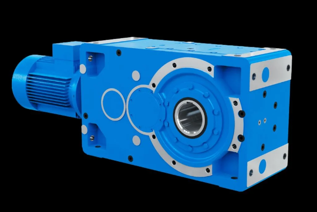
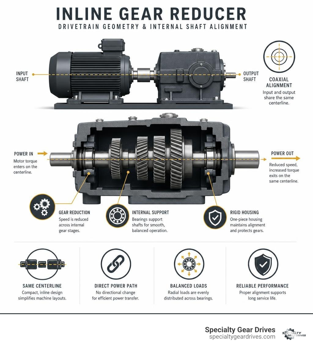
An inline speed reducer features input and output shafts that share the exact same centerline or sit on coplanar parallel centerlines. Power enters from an electric motor, routes through intermediate gear stages within a rigid casing, and exits on that identical axis.
This coaxial drivetrain architecture gives machine designers direct mechanical advantage without the offset bulk of parallel-shaft drives or the right-angle turn of bevel and worm units. Collinear shafts simplify machine frames, eliminate complex external linkages, and deliver balanced radial load distribution across internal bearing sets.

Where right-angle gearboxes redirect torque 90 degrees using bevel or worm sets, inline units drive straight through. Worm drives trade mechanical efficiency for high single-stage reduction through sliding friction, whereas inline gearboxes use rolling tooth contact that saves significant power. Parallel-shaft reducers offset the driven load to the side, demanding wider structural bases. Inline housings pack maximum torque density into a slender footprint, making them easy to drop between conveyor frames, under mixing tanks, or into compact skid packages.
Inline Helical Gear Drives
Helical gearing represents the backbone of modern inline industrial drives. Unlike straight-cut teeth that engage all at once across their entire face, helical teeth engage progressively along an angled contact line. This smooth transfer generates a high contact ratio, dampens vibration, and lowers operating noise under continuous heavy loads.
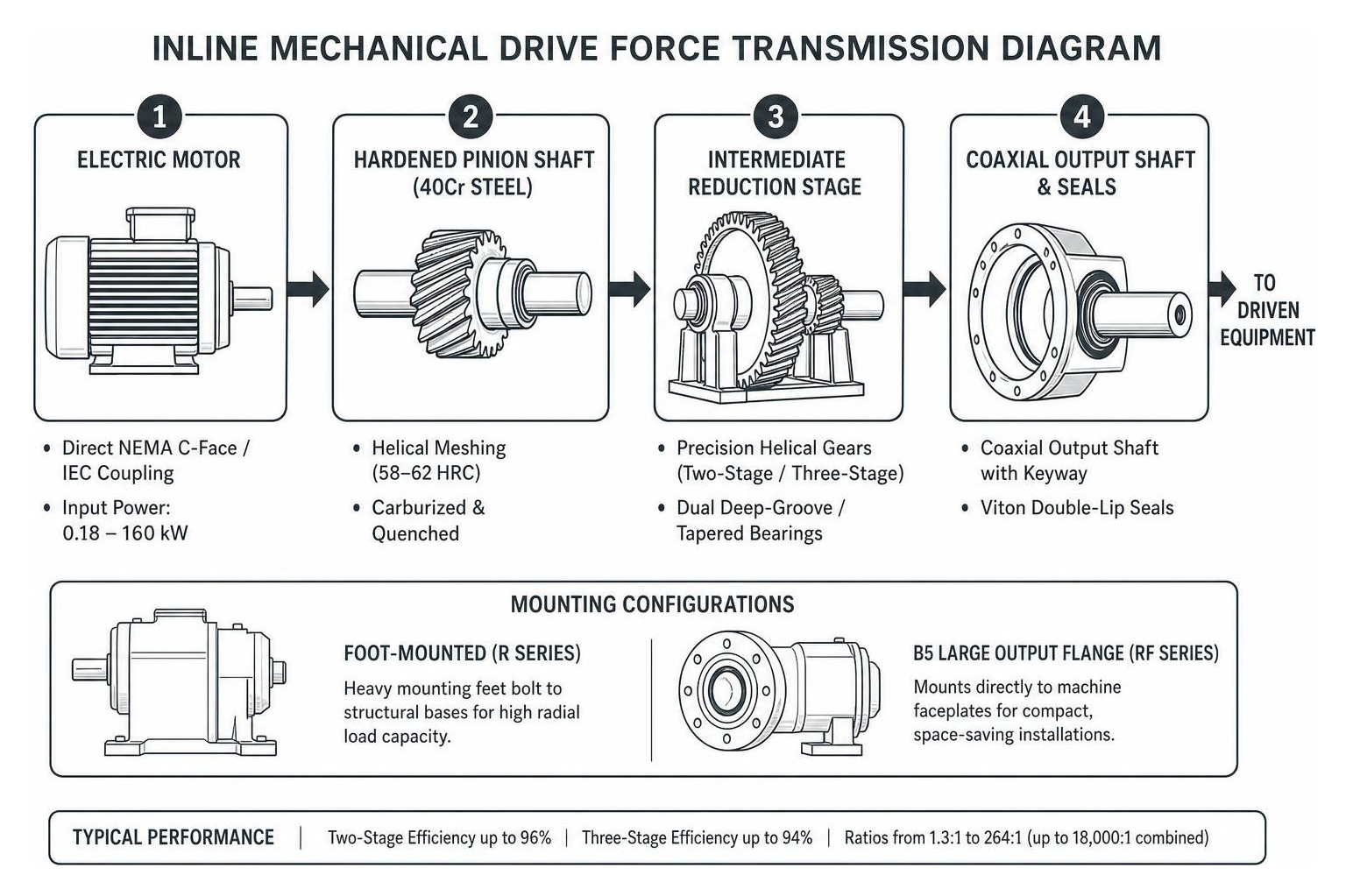
Two-stage inline helical configurations achieve transmission efficiency levels of 96% across typical ratios between 5:1 and 24.8:1. Three-stage models maintain roughly 94% efficiency across broader ratios extending past 200:1. We cut and finish precision gearing from case-hardened alloy steels such as 20CrMnTi, carburizing the contact surfaces and finish-grinding the flanks to ISO Grade 5 or 6 standards. Industrial units built with these methods handle demanding torque outputs up to 18,000 Nm across motor inputs from 0.18 kW up to 160 kW. When standard catalog replacements cannot meet unusual dimensional demands, custom gear manufacturing provides a direct path to match existing production machinery without rebuilding surrounding structures.
Inline Planetary and Spur Gear Reducers
Epicyclic or planetary inline gear drives take a different internal approach. A central sun gear meshes with multiple planet gears held within an internal ring gear. This layout divides incoming torque across multiple gear meshes at once, yielding massive torque capacity in a remarkably small volume. Inline planetary units handle input power from 0.5 HP through 40 HP, with single and dual stages delivering ratios from 3:1 to 25:1, while multi-stage configurations easily exceed ratios of 1000:1. They provide exceptionally low backlash, frequently down to 3 arc-minutes, making them common on precision positioning equipment and steady-pull drives.
Inline spur gearboxes use straight-cut cylindrical teeth mounted on parallel internal shafts. They provide clean speed reduction up to 4,000 RPM input speeds and torque ranges from 0.13 Nm to 90 Nm, reaching 92% efficiency at 1,000 RPM. Because spur gear teeth mesh without axial thrust loads, low-ratio spur boxes can also run backwards as speed increasers.
| Reducer Type | Transmission Efficiency | Standard Ratio Range | Operating Noise | Torque Density | Primary Industrial Fit |
|---|---|---|---|---|---|
| Inline Helical | 94% – 96% | 1.3:1 to 264:1 (up to 18,000:1 combined) | Very Low (< 70 dBA) | High | Conveyors, agitators, heavy processing lines |
| Inline Planetary | 90% – 97% | 3:1 to 25:1 (up to 1000:1+ compound) | Moderate to Low | Very High | High-torque compact drives, positive displacement pumps |
| Inline Spur | 88% – 92% | 1:1 to 625:1 | Moderate to High | Moderate | High-speed drives, automation, speed increasers |
Technical Specifications, Metallurgy, and Mounting Configurations
Drivetrain durability depends on metallurgy and structural stiffness. Heavy industrial inline gear reducers rely on fine-grain HT250 cast iron housings. Thick cast walls damp gear vibration and keep shaft centerlines rigid under shock loading.
Intermediate drive shafts machined from 40Cr alloy steel undergo carburizing and quenching to resist cyclic bending stresses. Gear teeth receive deep case carburization (0.6 to 1.5 mm case depth), creating a hard outer surface of 58–62 HRC for wear resistance, supported by a shock-absorbing core hardness of 33–48 HRC. Double-lip Viton seals keep contaminants out while containing high-film-strength lubricants. Direct-mount NEMA C-face input flanges (such as 56C, 145TC, 182/184TC, through 364/365TC) and IEC motor adapters eliminate open couplings, keeping motors aligned with the gearbox bore. Detailed metallurgical standards can be explored further in the complete guide to custom industrial gears.
Mounting Orientations and Output Configurations
Standard inline reducers offer several mounting styles to match machine layouts:
- Foot-Mounted (R Series): Heavy mounting feet cast into the base plate bolt directly onto structural machine beams, absorbing high downward radial reaction loads.
- B5 Large Output Flange (RF Series): Mounts directly against machine faceplates, common on agitators, augers, and wall-hung drives.
- B14 Face Mount: Offers compact threaded bolt patterns for direct machine integration where outer clearance is tight.
- Extended Bearing Hub (RM Series): Features an elongated cast iron output snout with widely spaced heavy-duty roller bearings. This design handles the punishing bending moments and overhung radial loads generated by long, unsupported mixer and agitator shafts without requiring external pillow blocks.
Industrial gear reducers support universal mounting orientations designated as M1 through M6.
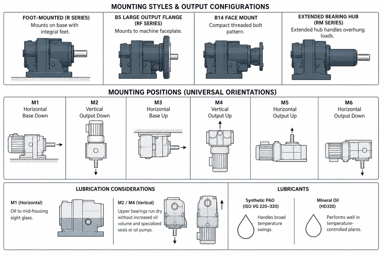
Mounting positions affect lubricant levels. A gearbox mounted horizontally (M1) requires oil up to its mid-housing sight glass. When installed vertically with the shaft pointing down (M2) or up (M4), upper bearings run dry unless oil volumes are increased and specialized grease-purged upper seals or oil pumps are incorporated. Synthetic PAO lubricants (ISO VG 220 to 320) handle broad temperature swings, while standard mineral oils (such as HD320) perform well in temperature-controlled plants.
Heavy Industrial Applications and Operating Environments
Continuous production environments demand stable speed reduction that runs without constant intervention. In continuous bulk material handling, inline helical drives power long overland conveyors, stacker-reclaimers, and steep bucket elevators. These lines require high starting torque to get fully loaded belts moving from a dead stop under hot, dusty conditions.
Positive displacement pump drives in chemical facilities rely on inline planetary and helical units to maintain steady, pulse-free output torque against variable head pressures. In pulp and paper mills, wastewater treatment plants, and chemical processing operations across Georgia, Alabama, Mississippi, and Louisiana, inline reducers run large fluid agitators and paddle mixers around the clock.
Aggregates, mining, and cement plants subject inline drives to severe shock loads on rock crushers, vibrating sizing screens, rotary kilns, and ball mills. In these environments, airborne abrasive dust makes housing rigidity, precision sealing, and clean oil filtration critical.
Engineering Selection and Lifecycle Maintenance
Matching an inline reducer to an industrial application requires evaluating mechanical capacity, thermal dissipation limits, and operating cycles. Mechanical power ratings (from 0.12 kW to 160 kW) reflect tooth shear and pitting limits, while thermal ratings define how much heat the housing can radiate before oil breaks down. In warm Gulf Coast plant environments across South Carolina, Florida, and Louisiana, ambient temperatures can quickly push an overloaded unit past its 200°F (93°C) oil sump limit, necessitating cooling fans or synthetic lubricants. Skipping overhung load checks or ignoring oil levels are common gear reducer repair mistakes you can’t afford to make during initial installation.
Sizing an Inline Gear Reducer for Industrial Duty Cycles
Sizing an inline drive involves five straightforward engineering steps:
- Calculate the Exact Speed Ratio ($i$): Divide motor input speed (typically 1,750 RPM for a standard 4-pole 60 Hz motor) by required driven equipment speed.
- Determine Running Load Torque ($T_L$): Calculate working torque from driven machine horsepower demand and target output speed: $$TL = \frac{\text{HP} \times 5252}{\text{RPM}{\text{out}}} \quad (\text{lb-ft}) \quad \text{or} \quad TL = \frac{\text{kW} \times 9550}{\text{RPM}{\text{out}}} \quad (\text{Nm})$$
- Apply the Service Factor ($SF$): Select an appropriate factor based on operational severity:
- Uniform Load (8–10 hrs/day): $SF = 1.0 \text{ to } 1.1$
- Moderate Shock (Conveyors, Agitators, 24 hrs/day): $SF = 1.4 \text{ to } 1.5$
- Heavy Shock (Crushers, Reciprocating Pumps, Mill Drives): $SF = 1.8 \text{ to } 2.2+$
- Select Gearbox Frame Size: Multiply load torque by the service factor ($T_{\text{design}} = TL \times SF$) and choose a frame size with a rated catalog torque exceeding $T{\text{design}}$ by at least a 10% safety margin.
- Verify Overhung ($FR$) and Axial ($FA$) Loads: When driving external sprockets, pulleys, or unguided mixer shafts, calculate radial overhung loads to ensure they remain well within catalog bearing limits. If you are troubleshooting an existing unit that ran hot or stripped teeth, review everything you need to know about gearbox repair to address root causes before sizing a replacement.
Inline Gear Reducer Maintenance and Wear Troubleshooting
Predictive maintenance protects equipment against catastrophic failure. Regular oil sampling reveals internal health before teeth strip or bearings seize. We recommend checking ISO VG 220 or 320 oil condition every 2,500 operating hours, screening for particulate contamination, viscosity loss, and moisture content.
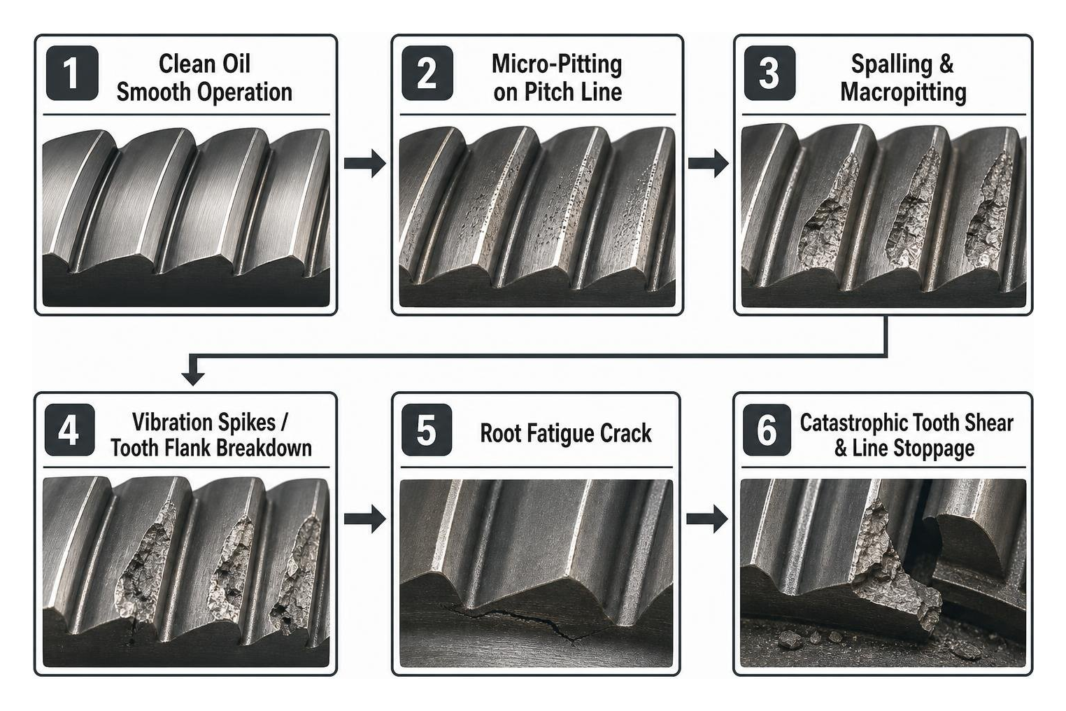
Common mechanical failure modes on inline reducers include:
- Tooth Micro-Pitting & Macropitting: Originates near the pitch line from thin oil films, incorrect viscosity, or abrasive debris. Left unchecked, small pits expand into deep spalls that fracture entire tooth flanks.
- Bearing Race Spalling: Manifests as high-frequency vibration spikes. Caused by excessive overhung belt tension, misalignment, or operating past $L_{10h}$ bearing life.
- Seal Leakage & Shaft Grooving: Hard grit gets trapped under elastomer lips, wearing a groove into the shaft surface and draining the oil reservoir.
- Backlash & End Play Growth: Worn taper roller bearings allow internal shafts to shift axially, degrading tooth contact patterns. For complete overhaul workflows, consult the ultimate guide to gearbox rebuild.
Frequently Asked Questions About Inline Gear Drives
What is the primary efficiency advantage of an inline gear reducer over a worm drive?
Inline helical and planetary reducers use rolling contact between precision-ground gear teeth, delivering 94% to 96% mechanical transmission efficiency across multiple stages. Worm drives transfer torque through sliding friction between a steel worm and bronze gear, losing significant power to friction. Worm efficiencies often hover between 50% and 85%, generating excess heat that requires larger motors and higher utility power to accomplish the same working output.
How do overhung and axial load limits affect inline reducer bearing life?
Overhung loads act as a lever arm on the output shaft, applying a radial force vector that concentrates stress directly on the front bearing. Most standard inline reducers can only absorb an axial thrust load equal to roughly 5% of their total rated radial capacity. Exceeding these forces causes roller bearing deflection, skews internal tooth contact patterns, and shortens calculated $L_{10h}$ bearing life from years to weeks. High-overhung agitators and mixers require extended bearing hub (RM series) housings.
Can an inline gear reducer be run in reverse as a speed increaser?
Spur and low-ratio helical inline gearboxes (ratios between 1:1 and 5:1) can be driven backwards as speed increasers because their high rolling efficiency permits backdriving without mechanical lockup. Driving a gearbox in reverse multiplies input speeds into the thousands of RPM, which can throw oil away from critical gear meshes, cause rapid seal friction wear, and exceed bearing thermal dissipation limits. High-speed reverse driving requires careful review of bearing ratings and forced lubrication.
Conclusion
Inline gear reducers deliver high efficiency, quiet operation, and rugged torque multiplication in a compact footprint. When heavy processing lines in mining, marine transport, cement production, wind generation, or bulk manufacturing encounter gear wear, full replacement is rarely the only path. Our facility in Largo, Florida provides comprehensive reverse engineering, gear cutting, and in-house line boring, returning worn equipment to exact OEM tolerances while delivering up to 60% savings compared to purchasing new units. We support heavy industrial operations throughout Florida, Georgia, South Carolina, Alabama, Mississippi, and Louisiana with rapid 24–48 hour emergency response, expedited logistics, free pickup and delivery, and a complete 24-month warranty on every rebuild. Reach out to our engineering team today for professional industrial gearbox repair and get your critical plant assets back into dependable service.