Ultimate Checklist for Selecting a Gear Reducer Gearbox
Core Mechanics and Types of a Gear Reducer Gearbox
Torque density defines how much rotational force an enclosed drive delivers relative to its physical frame size. When an electric motor couples to a gear drive, the internal gear train trades rotational velocity for mechanical advantage. Because AC induction motors typically operate at base speeds of 1200, 1800, or 3600 RPM, driven equipment like bucket elevators, kiln drives, and heavy slurry pumps require this input RPM reduction to function without destroying mechanical components.
Matching the drive to the prime mover involves standardized mechanical interfaces. NEMA C-face motor mounting (common across frame sizes like 145TC, 215TC, and 365TC) and IEC standard metric flanges (such as B5 and B14 configurations) allow direct motor connection. This direct coupling eliminates alignment errors associated with external belt or chain drives, preserving gear mesh alignment and preventing uneven bearing wear.
| Gear Reducer Type | Typical Stage Efficiency | Common Ratio Range | Primary Shaft Orientation | Common Industrial Applications |
|---|---|---|---|---|
| Inline Helical | 94% – 98% | 1.3:1 to 247:1 | Coaxial / Inline | Material handling, agitators, packaging lines |
| Parallel Shaft Helical | 94% – 98% | 3.5:1 to 280:1 | Parallel Offset | Belt conveyors, paper mill roll drives, cranes |
| Helical-Bevel | 92% – 95% | 5:1 to 200:1 | Right-Angle ($90^\circ$) | Crushers, bucket elevators, cement clinker feeds |
| Worm Gear | 50% – 90% | 5:1 to 60:1 (single) | Right-Angle Non-Intersecting | Winches, small hoists, low-speed positioners |
| Planetary | 95% – 97% | 3:1 to 100:1+ | Coaxial | Continuous mixers, heavy extruders, slewing drives |
| Cycloidal | 85% – 92% | 6:1 to 119:1 (single) | Coaxial | Robotics, dynamic feeder drives, positioning tables |
Gear Reducer vs Enclosed Gearbox Architecture
The terms speed reducer and enclosed gearbox describe related mechanical assemblies, yet their engineering scope differs. An enclosed gearbox refers to any rigid housing containing an isolated set of gears. This mechanism can reduce rotational speed, increase shaft speed (as seen in wind turbine utility drives), or alter output velocity via multi-ratio shifting assemblies.
A speed reducer is purpose-built strictly for deceleration. It decreases output speed while amplifying torque based on a fixed ratio determined by the relationship between the drive gear tooth count and the driven gear geometry. These units often ship as integrated gearmotors—combining the electric motor and the mechanical gear stages into a single unit. In multi-stage reductions, compound gear arrangements step down the speed across sequential intermediate shafts, dividing the mechanical load across hardened gear meshes to manage surface fatigue.
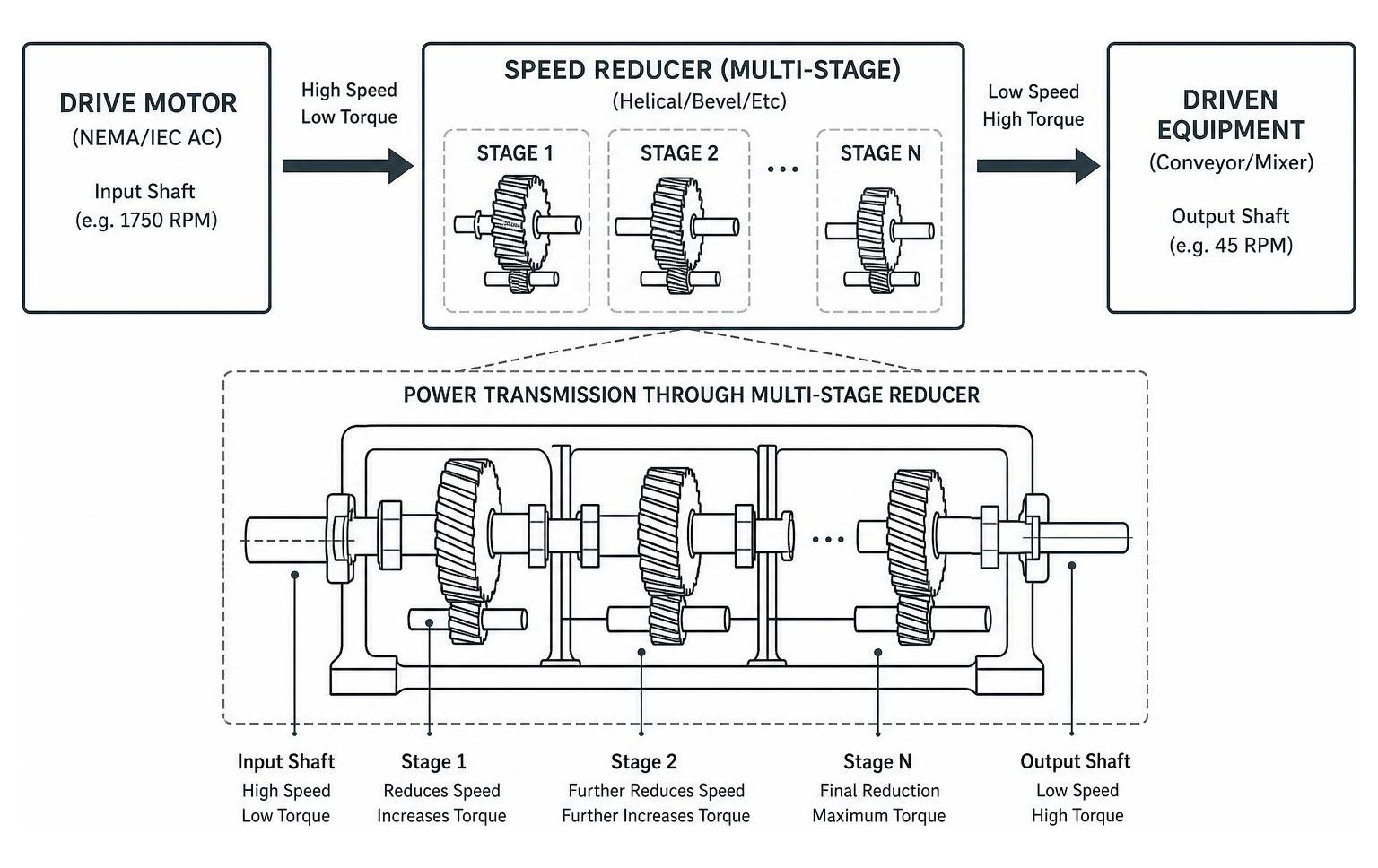
Helical, Bevel, Spur, and Worm Gear Configurations
Helical gears rely on teeth cut at an angle to the gear face. As the teeth mesh, contact begins at one end of the tooth and spreads gradually across the face width. This progressive engagement distributes the mechanical load, allowing helical stages to reach up to 98% efficiency per stage while holding noise levels under 65 dB(A). Industrial units commonly utilize 20CrMnTi or similar alloy steels, carburized and quenched to a surface hardness of HRC 58–62 with a ductile core (HRC 33–40) to absorb severe cyclic stress. Understanding tooth profiles and metallurgy is critical, as detailed in our guide on The Complete Guide to Custom Industrial Gears.
Straight-cut spur gears offer high efficiency (around 93% at 1,000 RPM) with zero axial thrust generation, but their simultaneous tooth-face impact produces significant operational noise and higher vibration at elevated speeds.
Right-angle drives typically employ bevel or worm configurations:
- Bevel & Helical-Bevel: Spiral bevel sets feature curved, oblique teeth that transfer torque around a 90-degree corner with minimal energy loss (typically 92% to 95% efficiency). They resist tooth breakage under moderate shock loads.
- Worm Gearing: Worm drives mate a hardened steel worm screw with a bronze worm wheel. They offer large reduction ratios (up to 60:1 in a single stage) in a small footprint. Their sliding tooth contact generates substantial friction, dropping efficiency to 50%–85% and shedding heat into the casing. At ratios exceeding roughly 30:1, the gear geometry resists backdriving from the output shaft, providing a hold-in-place characteristic for specific lifting or conveying machinery.
Planetary and Cycloidal High-Density Drives
Planetary (epicyclic) drives split the operational load across a central sun gear, multiple planet gears, and an internal ring gear. By sharing torque across three or four planetary meshes simultaneously within a coaxial housing, planetary reducers offer substantial torque density and stage efficiencies between 95% and 97%. When fitted with precision-ground helical planetary sets and preloaded tapered roller bearings, they deliver ultra-low backlash (down to $\le 1.5\text{ arcmin}$), making them common in high-demand automated material handling systems.
Cycloidal speed reducers discard traditional gear teeth altogether. They use an eccentric cam that drives a cycloidal disc against a stationary ring of pin/needle bearings and cam followers. Because several cycloidal lobes share the applied torque simultaneously, these units tolerate shock loads up to 500% of their baseline rating without tooth shear, maintaining smooth torque delivery in demanding positioning and continuous bulk-processing systems.
Essential Selection Criteria and Sizing Factors
Specifying a drive for an industrial facility requires reviewing operating parameters beyond nominal horsepower. Operating duty cycles dictate the cumulative thermal load and mechanical wear rate on rotating elements. Continuous 24/7 processing demands higher thermal dissipation thresholds than intermittent 8-hour shift cycles.
Overhung load (OHL) capacities determine how much radial force the input and output shafts can sustain from external sprockets, sheaves, or pinion gears without deflecting the shaft or overloading the bearings. In cement mills, pulp and paper facilities, and chemical processing operations throughout Alabama, Mississippi, and Georgia, ambient humidity, dust ingress, and thermal swings require sizing margins that prevent accelerated thermal degradation of internal components.
Precision Sizing of a Gear Reducer Gearbox
Precision sizing begins by calculating the absolute kinematic transmission ratio:
$$\text{Target Ratio} = \frac{\text{Motor Input RPM}}{\text{Required Output Shaft RPM}}$$
Next, apply the correct AGMA (American Gear Manufacturers Association) service factor based on the operational shock profile and daily run time:
- Uniform Continuous Load (1.00 – 1.25): Liquid agitators, belt conveyors with steady feed, automated packaging machinery.
- Moderate Shock Load (1.25 – 1.75): Heavy slurry mixers, rotary kilns, log debarkers, paper mill winders.
- Heavy Shock / Reversing Load (1.75 – 2.50+): Primary crushers, vibrating screeners, shredders, ball mills.
Calculate the design torque by multiplying the nominal application torque by the selected service factor:
$$\text{Design Torque } (T_{\text{design}}) = T_{\text{nominal}} \times \text{Service Factor}$$
Standard industrial units cover rated capacities from 0.18 kW up to 160 kW, supporting input speeds up to 3000 RPM and delivering output torque ratings past 18,000 Nm. When high shock loads or unusual torque spikes exceed standard off-the-shelf limits, facilities often turn to Custom Gear Manufacturing to cut gear geometry to non-standard center distances and load ratings.
Mounting Configurations for a Gear Reducer Gearbox
Physical mounting orientation directly affects housing stress, shaft alignment, and internal oil bath distribution:
- Foot-Mounted (Base Mount): Bolted directly to a structural steel bedplate or concrete foundation. This setup provides rigid anchoring against high radial loads, though it requires precise laser alignment with the driven machine shaft.
- Shaft-Mounted (Hollow Bore): Slides directly over the driven equipment’s head shaft, anchored by an external torque arm. This arrangement eliminates external couplings and alignment issues while absorbing mechanical flex in heavy conveyor systems.
- Flange-Mounted (IEC B5 / B14): Bolts directly to the machine frame or motor face, saving floor space in vertical mixers and agitators.
The shaft configuration must match the physical footprint of the plant floor:
- Coaxial (Inline): Input and output shafts share the same centerline, saving lateral width.
- Parallel Shaft: Input and output shafts run parallel but offset, allowing tight integration alongside conveyor frames.
- Right-Angle (Orthogonal): Shafts meet at 90 degrees, turning the motor package parallel to the machine line to preserve walkway clearances.
In heavy vertical mixing or extrusion applications, molten material backpressure or vertical fluid weight generates high axial thrust loads. Selecting an output housing with integrated spherical roller thrust bearings isolates these forces, keeping axial loads off the internal helical teeth and preventing premature bearing race failure.
Backlash, Noise Control, and Environmental Sealing
Backlash—the clearance between non-working tooth flanks in a meshed gear set—governs positioning precision and dynamic shock transmission during load reversals. For machine tools and precise indexing drives, gear teeth ground to ISO Class 6 accuracy minimize backlash to under 20 arcminutes (or down to $\le 1.5\text{ arcmin}$ for precision planetary sets).
Housing material selection plays an active role in structural damping. High-density HT250 gray cast iron dampens acoustic vibration and absorbs mechanical chatter better than welded sheet steel or lightweight cast aluminum. Precision grinding keeps total operating noise under 68–75 dB(A) even under heavy industrial loads.
For operations exposed to abrasive clinker dust, chemical vapors, or marine washdowns across coastal Florida and Louisiana, enclosures with IP65 ingress protection are standard. Adding labyrinth dual-lip viton seals and pressure-equalizing desiccant breathers blocks water and grit while preventing internal pressure spikes that push oil past the shaft seals.
Proactive Maintenance, Rebuilding, and Lifecycle Optimization
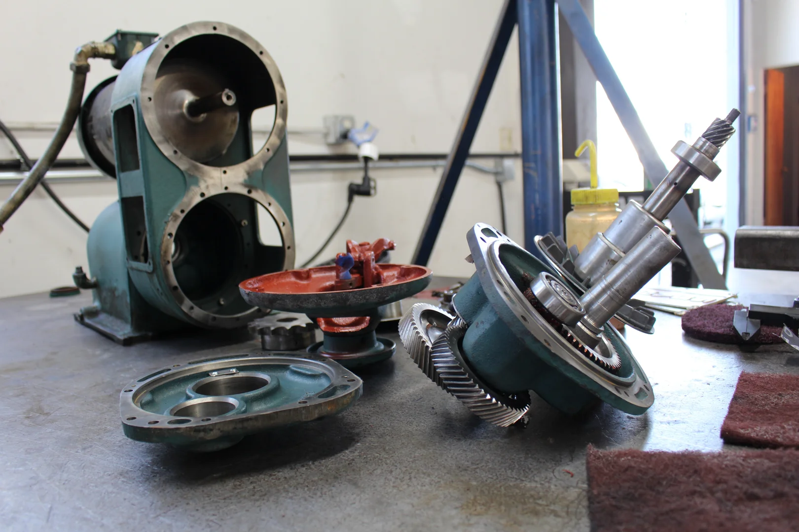
A regular maintenance program prevents sudden mechanical breakdowns. During the initial 500-hour run-in period of a newly commissioned or rebuilt unit, microscopic machining peaks on gear teeth shear off and suspend in the oil. Running that initial lubricant through a fine external filtration loop or performing a complete early drain purges this particulate before it acts as a lapping compound across bearing raceways.
Ongoing oil sampling and condition monitoring track the root causes of failure, letting maintenance teams catch progressive gear tooth pitting, scuffing, and bearing spalling well before catastrophic tooth fracture halts production.
Lubrication Regimes and Predictive Wear Monitoring
Maintaining a continuous elastohydrodynamic oil film across the tooth meshing zone prevents metal-to-metal contact under heavy contact pressure. Selecting the correct industrial gear oil—typically an ISO VG 220, 320, or 460 mineral oil (such as GB L-CKC series) or a synthetic Polyalphaolefin (PAO) / Polyalkylene Glycol (PAG)—depends on operating speeds and housing temperature rise.
As ambient casing temperatures rise above 40°C or oil sump temperatures pass 80°C, mineral oils oxidize rapidly, causing sludge formation and additive depletion. Synthetics maintain stable viscosity across wide operating temperatures, extending oil drain intervals and lowering internal fluid friction.
Pairing routine oil testing with spectral vibration analysis identifies internal problems early. Accelerometers mounted near bearing caps detect the high-frequency impact signatures of bearing cage wear, inner-race flaking, and gear mesh misalignment. For an operational look at early-warning systems, read How Gearbox Condition Monitoring Saves Your Machinery and Your Sanity. Avoiding common shortcuts during basic field servicing is equally important, as outlined in our review of Common Gear Reducer Repair Mistakes You Can’t Afford to Make.
Remanufacturing Economics and Precision Gearing Rebuilds
When heavy industrial units experience severe bearing distress, housing bore wear, or gear tooth spalling, procurement teams face a choice: wait months for a new OEM replacement or rebuild the existing asset. Remanufacturing an industrial speed reducer in a dedicated machine shop typically saves up to 60% compared to purchasing new equipment, while returning the unit to original factory tolerances.
A professional rebuild involves complete teardown, chemical degreasing, non-destructive crack testing (NDT), and dimensional verification:
- Line Boring: Worn or fretted bearing bores in gray cast iron housings are machined and sleeved back to OEM centerlines.
- Shaft Restoration: Damaged seal lands and bearing journals undergo thermal spray metallizing or sub-arc welding before precision cylindrical grinding.
- Gear Recutting and Grinding: Worn gear sets are reverse-engineered, gear-hobbed from high-alloy forgings, carburized, and finish-ground to precise tooth profiles.
Following dynamic spin-testing and blue-contact tooth pattern checks, a rebuilt drive delivers the service life of a new unit. To review the end-to-step remanufacturing workflow, consult The Ultimate Guide to Gearbox Rebuild.
Frequently Asked Questions About Industrial Gear Drives
What is the mechanical difference between a gear reducer and a gearbox?
An enclosed gearbox is a broad mechanical term encompassing any housed gear system designed to transmit rotational power. Gearboxes can reduce speed, increase speed (such as a 1:5 ratio speed increaser on a centrifugal blower), or shift through multiple gear ratios (like a multi-speed industrial transmission). A gear reducer is built specifically to decrease input shaft speed while multiplying output torque at a fixed ratio. While every speed reducer is a gearbox, not every gearbox operates as a reducer.
How does gear ratio selection affect output torque and speed?
The gear ratio establishes a direct, proportional relationship between input and output shaft performance. Ignoring small frictional heat losses, output speed drops by the exact divisor of the ratio, while output torque multiplies by the exact product of that same ratio:
$$\text{Output Speed } (N_{\text{out}}) = \frac{N_{\text{in}}}{\text{Ratio}}$$
$$\text{Output Torque } (T_{\text{out}}) = T_{\text{in}} \times \text{Ratio} \times \text{Mechanical Efficiency}$$
If a 1,750 RPM electric motor delivering 100 Nm of torque connects to a 10:1 helical speed reducer running at 96% mechanical efficiency, the output shaft turns at 175 RPM while delivering 960 Nm of torque.
Why are helical gear reducers preferred over worm reducers in heavy industry?
Helical units achieve mechanical transmission efficiencies between 94% and 98% per stage, whereas single-stage worm gearboxes often run between 50% and 85% efficiency due to continuous sliding tooth friction. In high-power industrial drives (from 15 kW to over 160 kW), that efficiency gap represents significant wasted electrical power and excessive heat dissipation. Helical gear teeth, manufactured from case-hardened 20CrMnTi alloy steel, also provide higher surface fatigue strength, lower operating temperatures, and longer gear life under continuous heavy service.
Conclusion
Selecting the right industrial drive requires balancing input speeds, mechanical ratios, overhung load ratings, housing orientations, and site environmental conditions. Sizing a drive properly keeps mechanical drives reliable across mining operations, cement mills, chemical plants, and heavy manufacturing facilities throughout the Southeast.
When heavy drives show signs of bearing wear, tooth pitting, or housing bore distress, Specialty Gear Drives provides complete overhaul and remanufacturing services. We handle rapid response logistics with free pickup and delivery across Florida, Georgia, South Carolina, Alabama, Mississippi, and Louisiana. All machining, line boring, gear cutting, and spin testing are performed completely in-house at our Largo, Florida facility, returning your critical assets to precise operational clearances with a 24-month comprehensive warranty.
Contact our engineering team to review your drive performance or schedule an overhaul: Industrial Gearbox Repair.