
A Comprehensive Guide to Worm Gear Speed Reducers
Engineering Principles of the Worm Gear Speed Reducer
At its mechanical foundation, a worm drive operates on a simple kinematic principle: an input shaft cut with helical screw threads (the worm) meshes directly with a conjugate toothed gear (the worm wheel or worm gear). Because the rotational axes sit perpendicular to each other on non-intersecting planes, the unit transmits mechanical power through a fixed 90-degree angle. Along with helical and bevel gearboxes, industrial gear reducers and speed reducers of this type provide critical torque transfer across conveyors, mining equipment, cement plants, marine systems, wind turbines, and heavy manufacturing lines.
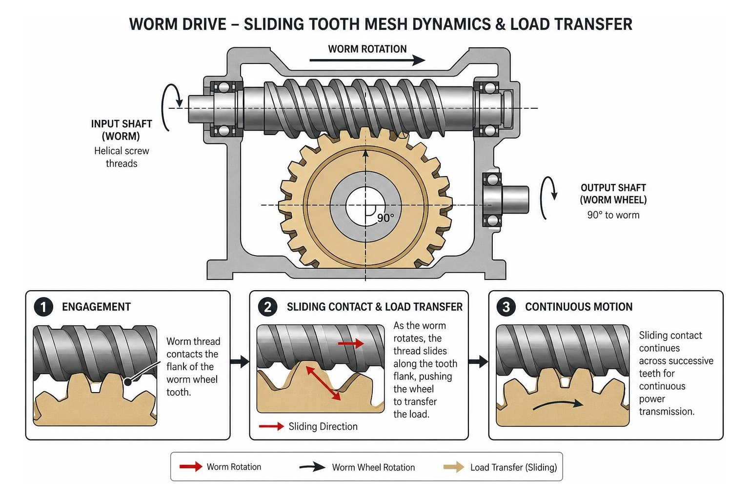
Unlike standard spur or helical gearing, which transfers energy predominantly through rolling contact along the pitch line, worm gear teeth experience pure sliding friction across their contact zones. The worm acts as an infinite driving ramp. As the screw turns, its threads push continuously against the flanks of the wheel teeth.
This continuous sliding action provides distinct operational advantages:
- Compact machine envelopes: High single-stage speed reduction ratios fit into narrow physical spaces where multi-stage parallel-shaft gearboxes would require massive footprints.
- Acoustic dampening: The absence of intermittent tooth impact eliminates gear chatter, making worm reducers exceptionally quiet under load.
- Shock load absorption: The expansive contact area between the worm threads and mating gear flanks distributes momentary impact loads across multiple teeth, resisting shock forces that could fracture standard spur gears.
Single vs Multi-Stage Worm Gear Speed Reducer Configurations
Standard single-reduction worm gearboxes support nominal ratios ranging from 5:1 up to 60:1 across stock center distances. Single reductions cover the vast majority of industrial power transmission tasks, matching standard 1750 RPM or 1170 RPM motor speeds to common equipment requirements.
When applications demand extremely slow output speeds combined with massive torque multiplication, multi-stage configurations combine gearsets in series:
- Single Reduction (5:1 to 60:1): Achieves dependable speed reduction in a single casing with fewer moving parts.
- Double Reduction (100:1 to 10,000:1): Combines two modular worm stages or a primary helical gear with a secondary worm gear, delivering output torques up to 2,670 Nm or higher for low-speed positioning systems.
- Triple Reduction (up to 175,000:1): Utilizes three consecutive gear reductions to deliver ultra-slow fractional RPMs for specialized heavy-industrial equipment, solar tracking arrays, and thick-slurry drive mechanisms. Facilities requiring non-standard center distances or custom replacement gearing benefit from dedicated Custom Gear Manufacturing to recreate obsolete stage ratios without replacing complete machinery drive assemblies.
Metallurgy and Component Design
Because the continuous sliding motion between mating teeth generates intense localized friction and heat, material pairing is critical to prevent catastrophic surface galling.
The driving worm is typically manufactured from case-hardened alloy steel (such as AISI 8620 or 4140). The threads are carburized, precision-ground, and polished to a mirror finish. This creates an extremely hard, smooth outer layer that resists abrasive wear.
In contrast, the driven worm wheel is cast from centrifugally cast phosphor bronze (often SAE 65 or CDA 907) or manganese bronze. Phosphor bronze offers low sliding friction against polished steel, high fatigue resistance, and excellent conformity. The bronze wheel acts as a sacrificial wear element. As the drive runs in under load, the softer bronze burnishes and work-hardens against the rigid steel worm threads, creating a customized contact profile that distributes contact pressure evenly. For specialized industrial drives, The Complete Guide to Custom Industrial Gears breaks down how alloy selection directly affects tooth life under continuous loading.
The structural housing is poured from heavy-duty gray cast iron (typically Class 30) or cast aluminum. Gray iron provides high structural rigidity to resist separating forces, excellent thermal dampening, and superior internal oil-sump heat absorption.
Mechanical Performance, Efficiency, and Self-Locking Dynamics
The mechanical efficiency of a worm gear drive depends on its lead angle, sliding velocity, tooth surface finish, and lubrication regime. As the gear ratio increases, the lead angle of the worm thread becomes shallower, forcing the contact mechanics further into a sliding friction regime.
A 5:1 reduction drive operates around 90% efficiency. That efficiency drops toward 50% when stepping down through a 60:1 ratio. The remaining input power converts directly into thermal energy within the oil bath, which must be dissipated through the gearbox housing.
Thermal vs Mechanical Ratings
Every worm gear speed reducer carries two distinct load ratings:
- Mechanical Rating: The physical power and torque limits the gear teeth, shafts, and bearings can support based on tooth pitting resistance, bronze fatigue limits, and shear strength.
- Thermal Rating: The maximum continuous input horsepower the gearbox can transmit without the oil bath temperature exceeding a 100°F rise above ambient air temperature.
In continuous industrial operations across the warm climates of Florida, Georgia, Alabama, South Carolina, Mississippi, and Louisiana, ambient plant temperatures can easily exceed 95°F. If a gearbox runs continuously at its mechanical limit, oil temperatures can surpass critical operating thresholds. Standard industrial gear lubricants break down rapidly above 200°F to 210°F, losing their boundary film strength and allowing accelerated bronze-on-steel wear.
When sizing drives for non-stop cycles, select the unit based on whichever rating is lower (which is almost always the thermal rating), or integrate housing cooling fans, external heat exchangers, and cooling ducts.
Self-Locking Capabilities and Dynamic Back-Driving
A common assumption in plant design is that a worm gear drive will automatically hold a suspended load without slipping. While static friction provides holding resistance at shallow lead angles (typically ratios above 50:1), relying on a worm gearbox as a primary safety holding device is dangerous.
Static friction drops drastically into dynamic friction the moment external forces initiate motion. Plant floor vibration, mechanical tremors from adjacent equipment, or structural movement can break static tooth friction. Once creep begins, friction plummets, and the load can accelerate into a catastrophic back-drive condition.
For cranes, winches, bucket elevators, and inclined conveyors, always install an independent electromechanical motor brake or mechanical backstop on the input shaft rather than relying on worm gear self-locking.
Conversely, units with steep lead angles (5:1 through 15:1) exhibit low sliding resistance and can be intentionally back-driven, allowing them to function as speed increasers in specialized equipment trains.
Selection and Sizing Criteria for Industrial Applications
Selecting an industrial speed reducer requires balancing input motor power, required driven torque, shock load characteristics, and daily operating hours. Standard stock units range from 1.33-inch to 3.25-inch center distances, while heavy process drives utilize center distances extending beyond 20 inches.
Many industrial installations use direct-coupled NEMA C-face input flanges (such as 56C, 145TC, or 184TC). These allow direct mounting of standard electric motors without external couplings or alignment brackets, reducing setup errors and minimizing operational downtime. When sizing gear reducers for replacement or overhaul, reviewing Common Gear Reducer Repair Mistakes You Can’t Afford to Make helps prevent common sizing and installation oversights.
Sizing Calculations for a Worm Gear Speed Reducer
To determine the correct reducer frame size, calculate the design torque by applying an AGMA service factor to the actual machine load:
Calculate Required Output Torque ($T_{out}$): $$T_{out} \text{ (lb-in)} = \frac{\text{Horsepower} \times 63,025}{\text{Output RPM}}$$
Apply AGMA Service Factor ($SF$):
- Uniform load (8-10 hrs/day): $SF = 1.00$
- Moderate shock (conveyors, agitators, 24 hrs/day): $SF = 1.25 \text{ to } 1.50$
- Heavy shock (mining crushers, shredders, reversing feeds): $SF = 1.75 \text{ to } 2.00+$
Determine Design Torque: $$T_{\text{design}} = T_{out} \times SF$$
Calculate Motor Input Horsepower Requirement: $$\text{Input HP} = \frac{T_{out} \times \text{Output RPM}}{63,025 \times \text{Mechanical Efficiency}}$$
Momentary peak starting loads must not exceed 300% of the reducer’s nominal mechanical rating, and momentary overloads should be limited to durations under two seconds. When evaluating equipment overhauls, following A Practical Guide to Precision Gearbox Rebuild Service ensures that load parameters align with internal shaft and bearing capacities.
Mounting Positions and Shaft Configurations
Worm gear reducers operate in multiple standard mounting orientations:
- Worm Below Gear (Horizontal Floor Mount): Submerges the high-speed input worm in the oil bath, providing lubrication for high-speed shafts.
- Worm Above Gear: Elevates the worm above the oil sump, reducing fluid churning losses at input speeds above 1800 RPM while relying on the gear wheel to dip and carry oil upward.
- Vertical Output (Shaft Up or Down): Common on mixers, agitators, and rotary tables. This orientation requires drywell construction or secondary lower seals to prevent fluid from escaping around the downward output shaft.
Output shafts are available in solid single-ended, double-ended, or hollow bore configurations. Hollow bore units slip directly over the driven machine’s head shaft and anchor via a torque arm, eliminating flexible couplings and pillow block alignment challenges.
Always reposition the oil fill, drain, and pressure breather plugs to match the chosen mounting orientation. Installing a breather plug below the operating oil level causes immediate lubricant blowout once thermal expansion pressurizes the housing.
Lubrication Practices, Preventative Maintenance, and Rebuilding
Lubrication dictates the service life of every worm gearbox. Because the sliding contact constantly wipes the fluid film off mating teeth, standard mineral hydraulic oils or automotive gear oils will fail.
Industrial worm drives require specialized heavy-bodied lubricants:
- Compounded Gear Oils (AGMA 7 Compounded / 8 Compounded): High-viscosity mineral oils blended with 3% to 10% natural fatty additives. These fatty acids plate out on bronze surfaces to form a sacrificial low-shear boundary layer.
- Polyalphaolefin (PAO) Synthetics (ISO VG 460 to ISO VG 680): High-viscosity synthetic fluids that resist thermal oxidation and provide wide operating temperature windows.
- Polyalkylene Glycol (PAG) Synthetics: Deliver low friction coefficients, superior lubricity, and high thermal capacity. Caution: PAG oils are incompatible with standard mineral oils, certain shaft seal elastomers, and internal housing paints.
Never use active sulfur-phosphorus Extreme Pressure (EP) gear oils in worm gearboxes containing bronze wheels. Under localized frictional heat, active sulfur chemicals attack yellow metals, causing rapid copper leaching, corrosive tooth pitting, and catastrophic tooth thinning. For step-by-step fluid management guidelines, reference Everything You Need to Know About Gearbox Repair to establish plant maintenance protocols.
Backlash Tolerances and Tooth Contact Alignment
Maintaining proper backlash and tooth contact patterns prevents premature gear failure. Backlash provides running clearance for lubricant film circulation and accommodates the thermal expansion of the bronze wheel during continuous duty cycles.
Inspect tooth contact by applying Prussian blue compound across the driving worm threads and rotating the assembly under light braking drag. The initial contact pattern on the bronze gear tooth should rest on the leaving side (the side where the worm thread exits the gear tooth).

This deliberate leaving-side contact ensures that when full operating load deflects the worm shaft, the contact zone shifts toward the center of the tooth while preserving an entry-side wedge for incoming lubricant. Detailed teardown steps and shimming procedures are outlined in The Ultimate Guide to Gearbox Rebuild.
Troubleshooting Common Failures and Rebuild Solutions
When standard maintenance fails or units operate beyond thermal limits, specific failure modes arise:
- Bronze Tooth Spalling and Flaking: Indicates boundary film collapse, excessive operating temperatures, or abrasive contamination in the oil sump.
- Corrosive Pitting and Copper Stripping: Caused by using sulfur-phosphorus EP lubricants that corrode the phosphor bronze alloy.
- Bearing Spalling and Shaft Play: Tapered roller bearings lose preload due to housing wear or axial thrust overload, causing shaft deflection and destroying the gear mesh.
- Oil Seal Leaks: Heat hardens nitrile lip seals, causing groove wear on the shaft surface and fluid loss.
When a gearbox housing experiences bearing bore wear or seal surface scoring, replacement is not the only path forward. Complete precision overhauls, housing line boring, shaft fabrication, and custom bronze gear cutting can restore damaged units to original specifications. Maintenance teams can review the comprehensive workflow in How to Rebuild Gearboxes Step by Step Guide to evaluate repair options.
All precision line boring, thermal sleeve fitting, welding, gear cutting, and assembly work at Specialty Gear Drives is executed entirely in-house at our Florida facility. We provide free pickup and commercial freight logistics across Florida, Georgia, South Carolina, Alabama, Mississippi, and Louisiana, returning industrial speed reducers to active service with rapid shop turnarounds.
Frequently Asked Questions about Worm Gear Speed Reducers
Are worm gear speed reducers completely self-locking in lifting applications?
No. High-ratio worm reducers (ratios exceeding 50:1) exhibit high static friction that resists back-driving under resting conditions, but dynamic operating forces change this behavior. External machinery vibration, structural shock, or dynamic load shifts can break static tooth friction. Once initial micro-movement starts, sliding friction drops rapidly, allowing the load to drive the system backward. For lifting, hoisting, or inclined conveyor lines, always install an independent electromechanical brake on the motor input shaft.
Why do worm gear speed reducers experience lower efficiency at high reduction ratios?
Worm drives transfer power through continuous sliding friction rather than rolling contact. At higher gear ratios, the lead angle of the worm thread becomes shallower. This shallow angle increases the sliding distance and contact duration per revolution, converting a higher percentage of input mechanical energy into frictional heat within the oil bath.
What lubricant type is required for bronze worm gear reducers?
Bronze-wheel worm reducers require either AGMA 7/8 Compounded mineral oils blended with fatty acids or high-viscosity synthetic PAO/PAG lubricants (ISO VG 460 to 1000). Avoid standard automotive gear oils or industrial EP gear oils containing active sulfur-phosphorus additives, as they chemically attack bronze gear teeth under operating heat.
Conclusion
Worm gear speed reducers provide exceptional shock load absorption, quiet mechanical operation, and compact right-angle torque transmission across modern processing operations. By understanding their mechanical efficiency curves, matching thermal ratings to plant operating conditions, specifying proper non-EP lubricants, and monitoring tooth wear patterns, plant teams can ensure reliable operation across demanding industrial production environments.
When heavy-duty worm, helical, or bevel drives show signs of bearing wear, backlash widening, or tooth degradation, rebuilding restores critical production equipment to peak operating condition. Specialty Gear Drives delivers comprehensive industrial gearbox rebuilding, complete bronze gear re-manufacturing, and housing line boring performed 100% in-house at our Florida facility.
We support plant maintenance engineers and operations managers across Florida, Georgia, Alabama, South Carolina, Mississippi, and Louisiana with expedited logistics, 24–48 hour rapid-response shop turnaround, cost savings up to 60% compared to new OEM replacements, and an industry-leading 24-month operational warranty. Contact us through our dedicated Industrial Gearbox Repair team to schedule emergency logistics or request an in-house repair evaluation for your plant’s speed reducers.