When Worn Bores Stop Your Operation, Line Boring Machining Is the Fix
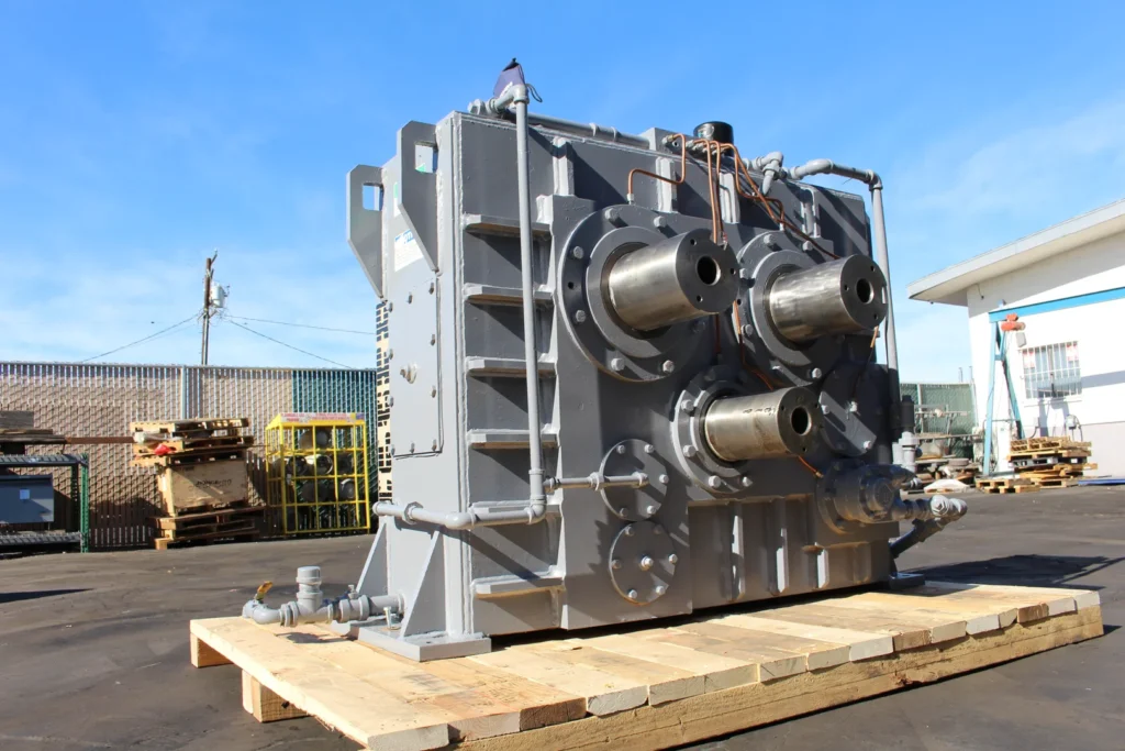
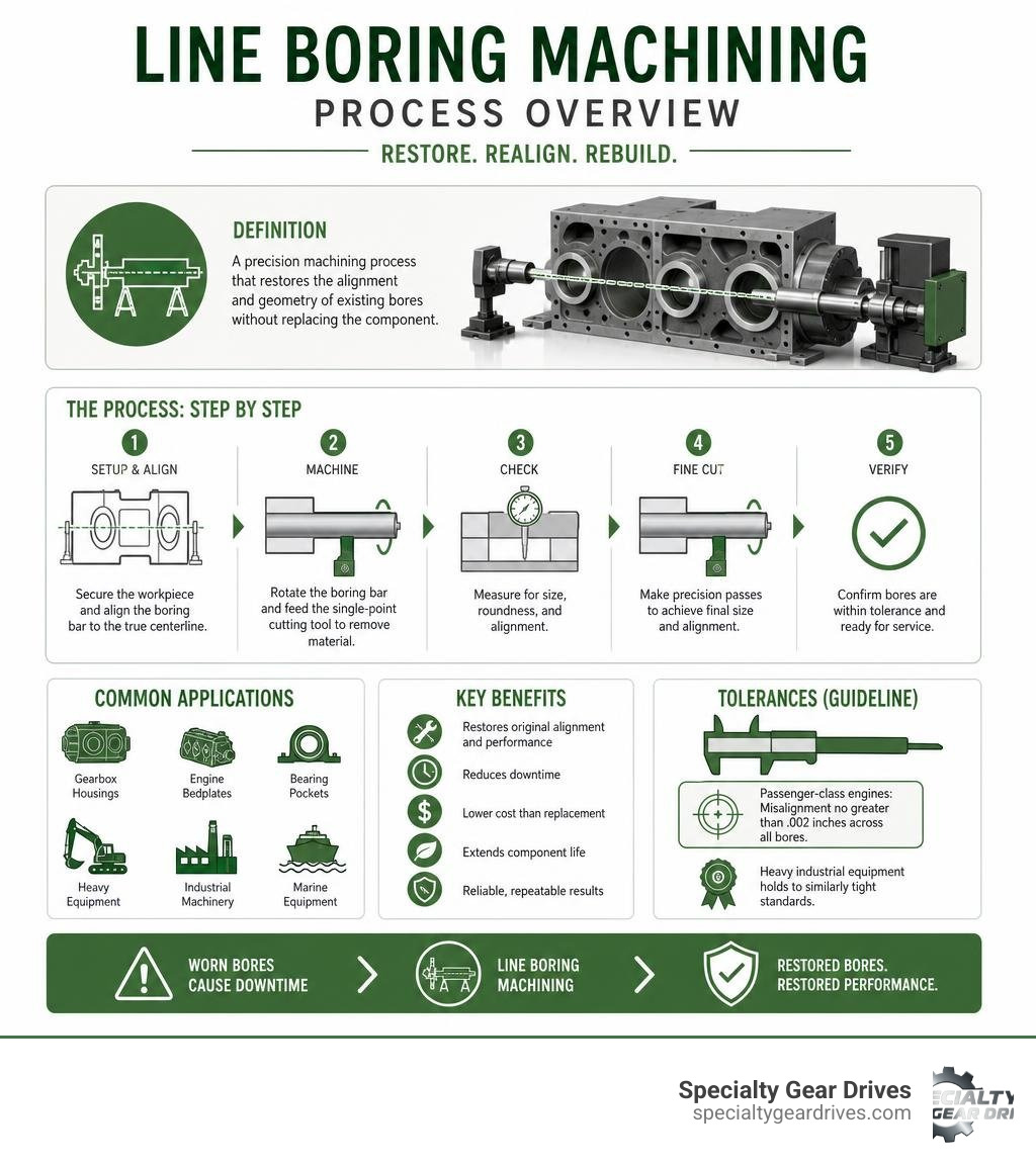
Line boring machining is a precision process that restores the alignment and geometry of existing bores in large industrial components, such as gearbox housings, engine bedplates, and bearing pockets, without replacing the entire casting.
Here is a quick breakdown of what it is and why it matters:
- What it does: Re-machines worn, out-of-round, or misaligned bores back to their original specifications
- How it works: A rotating boring bar is passed through the bore along a fixed centerline, removing material with a single-point cutting tool at a controlled feed rate and depth
- When you need it: When bore wear, overheating, bearing seizure, or heavy load cycling causes the bore to lose roundness or centerline alignment
- What it replaces: In most cases, a full housing replacement, which carries long lead times and high cost
- Who uses it: Maintenance teams in mining, pulp and paper, petrochemical, marine, and heavy manufacturing operations
A single worn bore in a gearbox housing can knock a conveyor line offline for days. For facilities across the Gulf Coast and Southeast, where heat, humidity, and continuous-duty cycles accelerate wear on drive systems, that kind of unplanned downtime is expensive. Line boring machining gives maintenance engineers a reliable path to restore a housing to OEM tolerances without the cost or lead time of sourcing a replacement casting.
The process is used on bore diameters ranging from 25mm to over 1,000mm, and on bore lengths up to 12 meters in some industrial configurations. Standard tolerances for passenger-class engines require misalignment no greater than .002 inches across all bores, and heavy industrial equipment holds to similarly tight standards. When a bore drifts outside those limits, machining is the answer.
Line boring machining terms to remember:
What is Line Boring Machining and How Does It Work?
Line boring is a specialized metal-cutting process used to enlarge, refine, and perfectly align a series of collinear holes. Unlike standard machining processes that focus on a single opening, line boring targets multiple internal diameters that must share a single, absolute centerline.
When heavy machinery operates under high torque, the bearing pockets and shaft tunnels in the housing experience constant stress. Over years of service, these bores stretch, warp, or wear out of round. To restore the equipment to service, we use housing line boring to bring the bearing seats back to their original dimensions and ensure the shafts run completely true.
To understand why this process is unique, it helps to compare it to drilling and standard boring. Drilling is designed to create a rough hole where none existed before. Standard boring enlarges an existing hole to improve its dimensional accuracy, but it does not guarantee that multiple holes separated by a gap will align with one another. Line boring solves the specific problem of coaxiality, ensuring that two or more bores separated by open space share the exact same axis.
| Machining Process | Primary Purpose | Tooling Type | Alignment Capability |
|---|---|---|---|
| Drilling | Creates a new, rough hole in solid material | Twist drill bit | Poor; tool follows path of least resistance |
| Standard Boring | Enlarges and rounds out a single existing hole | Single-point cutter on a stub bar | Moderate; depends on spindle rigidity |
| Line Boring | Aligns and sizes multiple inline bores | Boring bar supported by external bearings | Excellent; ensures absolute coaxiality across long spans |
The Mechanics of Line Boring Machining
The physical setup of a line boring operation determines its accuracy. The core of the system is the boring bar, a long, precision-ground steel shaft that passes directly through the bores being machined. This bar must be rigid enough to resist bending or deflection during the cutting process.
To maintain this rigidity over long spans, we place support bearings on both sides of the work area. These bearings hold the bar in a fixed position, preventing sag and vibration. Single-point cutting tools are secured in slots along the boring bar. As the bar rotates, a drive mechanism moves it axially through the bores at a calibrated feed rate.
Controlling the rotational speed and feed rate is critical to achieving the required surface finish and dimensional tolerances. If the speed is too high, the cutting tool heats up and wears prematurely, which can cause taper in the bore. If the feed rate is too fast, the surface finish will be rough, preventing the new bearings from seating properly. By carefully balancing these variables, we can machine bores to within ten-thousandths of an inch of the design specification.
Stationary vs Portable Line Boring: Choosing the Right Method
When a gearbox housing or industrial casting requires machining, we must decide whether to perform the work on a stationary machine in our shop or deploy portable equipment to the job site. Both methods have distinct structural and operational advantages depending on the size of the component and the urgency of the repair.
Stationary line boring is performed in a controlled workshop environment using large horizontal boring mills. This method provides the highest level of mechanical rigidity and allows us to use heavy-duty cutting heads and digital readouts for maximum precision. For gearboxes that can be easily disconnected, rigged, and shipped, workshop machining is the standard choice. You can learn more about our shop-based capabilities by reading about how to source services for a line boring gearbox housing.
Portable line boring, on the other hand, brings the machine tool directly to the equipment. Portable boring rigs are modular systems that mount directly to the face of the workpiece using bolt-on mounting plates and spherical bearing supports. This approach eliminates the need to transport massive castings, saving thousands of dollars in freight costs and reducing weeks of operational downtime.

When to Deploy Portable Line Boring Machining
Portable line boring is the preferred choice when the machinery is too large, heavy, or integrated into the plant infrastructure to be practical to move. In Gulf Coast petrochemical plants and paper mills across Alabama and Mississippi, rigging out a multi-ton gearbox housing might require cutting open a building wall or hiring specialized heavy-lift cranes. In these scenarios, machining the housing in place is the only viable option.
Common field applications include:
- Marine stern tubes and rudder stock pintle bores in coastal shipyards
- Steam, gas, and hydro turbine casings in power generation facilities
- Large drying cylinder bearings and press section housings in paper mills
- Pivot points, main frames, and boom hinges on heavy mining equipment
- Large industrial gearbox housings used in municipal water treatment and cement plants
Step-by-Step Guide to the Line Boring Process
Successfully machining a series of inline bores requires a systematic approach. Any shortcut taken during the setup phase will show up as a defect in the finished bore, leading to rapid bearing failure or shaft binding.
The first step is a thorough inspection of the damaged area. We clean the bores to remove oil, grease, and carbon buildup, then use dial bore gauges to measure the extent of the wear, taper, and out-of-roundness. If the bores are severely worn or cracked, we often perform how gearbox housing welding services restore damaged castings to build up the worn areas with fresh metal before we begin cutting.
Next, we establish the centerline using laser alignment systems or mechanical dial indicators. Once the centerline is verified, we set up the boring bar and support bearings, securing them to the housing using heavy-duty clamps or tack-welded brackets.
With the setup locked in, we begin the machining phase:
- ID Welding (Bore Build-Up): If the bore is oversized, an automated inner-diameter welding system deposits a uniform layer of weld metal along the worn surface.
- Rough Cutting: We configure the boring bar with roughing tools to remove the bulk of the excess weld material, bringing the bore to within roughly 0.030 inches of the final size.
- Semi-Finish Cutting: We take a lighter pass to correct any minor tool deflection and ensure the bore is perfectly round and straight.
- Finish Cutting: Using a sharp, precision-ground carbide or cobalt insert, we make the final pass at a slow feed rate to achieve the exact target diameter and specified surface finish.
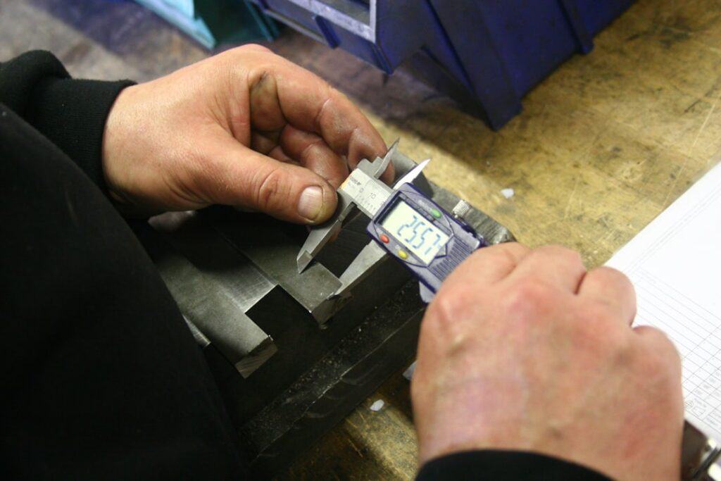
- Quality Control: We perform final measurements using calibrated micrometers and verify the alignment across all bores before removing the equipment.

Key Challenges: Machining Difficult Alloys and Maintaining Rigidity
Machining standard cast iron or carbon steel is straightforward, but industrial gearboxes and chemical vessels often use specialized alloys designed to resist corrosion and high temperatures. Materials like Hastelloy, Stellite, and high-nickel stainless steels present significant challenges for line boring technicians.
These alloys work-harden rapidly under the heat and pressure of cutting. If the tool rubs instead of cutting, the metal surface becomes incredibly hard, which quickly destroys the cutting edge. To machine these materials successfully, we must use high-torque drive motors that can maintain a slow, steady rotational speed under heavy loads. We also use 5% cobalt square tool bits or specialized carbide inserts with aggressive rake angles to ensure the tool slices through the material rather than pushing against it.
Maintaining structural rigidity is another constant battle, especially during field operations. When the boring bar is extended over a long span, even minor cutting forces can cause the bar to flex or vibrate. This vibration, known as chatter, ruins the surface finish and can chip the cutting tool. To prevent this, we place temporary support braces or intermediate bearings along the bar wherever possible. If we are machining an interrupted cut, such as a bore with an internal keyway or oil groove, maintaining rigidity is even more critical because the tool experiences a sharp impact every time it re-engages the metal.
Frequently Asked Questions About Line Boring
What is the difference between line boring and line honing?
Line boring uses a single-point cutting tool mounted on a rotating bar to remove significant amounts of metal and correct major alignment errors. Line honing, also known as align honing, uses a long mandrel fitted with abrasive stones to polish and finish the bores. Honing removes very little material, typically limited to 0.003 inches or less, and is used to achieve a highly polished surface finish and make micro-adjustments to the bore size after line boring is complete.
How much misalignment can line boring correct?
Line boring can correct virtually any amount of misalignment, provided there is enough structural material in the housing to allow for machining. If the bores are severely misaligned due to structural warping or thermal distortion, we weld the worn bores shut and machine them completely from scratch along the original OEM centerline. This process restores the alignment back to within the original design tolerances, which are typically less than 0.002 inches overall.
Why is line boring preferred over replacing the entire housing?
Repairing a housing through line boring typically saves up to 60% of the cost of purchasing a new component. Beyond the direct financial savings, lead times for large industrial gearboxes and custom castings can stretch into months. Line boring can often be completed in a matter of days, keeping your plant running and minimizing the massive costs associated with extended downtime.
Conclusion
When a critical drive system fails, you need a partner who understands the mechanical demands of heavy industrial equipment. At Specialty Gear Drives, we provide comprehensive industrial gearbox manufacturing and repair services for plants throughout Florida, Georgia, Alabama, South Carolina, Mississippi, and Louisiana.
Whether you are running a pulp and paper mill in Alabama, a petrochemical plant in Louisiana, or a municipal processing facility in Florida, our team is equipped to handle your most demanding machining needs. We back our work with a 24-month warranty and offer 24-48 hour emergency service to get your operations back online quickly. With free pickup and delivery across our service area, we make it easy to restore your equipment to peak performance.
If you have a gearbox housing showing signs of bore wear or shaft misalignment, contact us today to learn more about our Industrial Gearbox Repair services.