When a Gearbox Has No Blueprint: Why a Reverse Engineering 3D Scanner Changes Everything
A reverse engineering 3D scanner is the fastest way to recreate an accurate CAD model from a physical part when no original drawings exist. For industrial facilities dealing with obsolete gearbox components, worn housings, or discontinued OEM parts, that capability can mean the difference between a two-day repair and a two-month wait.
Here are the best 3D scanners and software tools for reverse engineering industrial components:
| Tool/System | Best For | Key Strength |
|---|---|---|
| Peel 3.CAD | All-in-one scanning + CAD bridge | 0.050 mm accuracy, built-in entity extraction |
| QUICKSURFACE Pro | Dedicated scan-to-CAD conversion | Handles ~100M triangles, Siemens Parasolid kernel |
| ZEISS Reverse Engineering | High-precision industrial metrology | Up to 50% fewer iteration loops in tool correction |
| EXModel | Mesh-to-parametric CAD conversion | One-click CAD generation from scan data |
| Artec/EINSTAR class scanners | Field scanning of worn or broken parts | Portable, captures 2 million data points per pass |
The core problem is this: a 3D scanner produces a polygon mesh or point cloud, not an editable CAD file. That raw scan data has to be processed through specialized software before it becomes something a machinist or CNC programmer can actually use. Understanding that gap, and knowing which hardware and software tools close it efficiently, is what this guide is about.
Plant engineers and maintenance managers at industrial facilities know the scenario well. A critical gearbox component fails. The OEM is out of business, the lead time is six months, or the part was custom-made decades ago with no surviving documentation. Traditional methods like calipers and manual measurement can capture basic dimensions, but they fall apart fast on complex castings, worn bearing bores, or organic housing geometries. A single failed measurement on a mating surface can mean a rebuilt part that doesn’t fit.
3D scanning addresses that directly. It captures the full surface geometry of a part in minutes, with typical accuracy around 0.05 mm for professional-grade systems. That data then feeds into CAD software where engineers can reconstruct a production-ready model, verify it against the original scan, and hand it off for machining or manufacturing.
How a Reverse Engineering 3D Scanner Redefines Industrial Part Replication
Using non-contact optical measurement transforms how we handle damaged or worn machinery. Instead of spending hours trying to measure complex internal curves with physical tools, we can project light patterns onto the object and record the reflections. This process captures millions of dimensional coordinates in seconds, creating a highly detailed digital replica of the physical part.
Industrial parts are rarely pristine when they arrive for repair. They suffer from physical wear, erosion, and structural deformation. When we scan a worn gear or a cracked housing, we are capturing its current state. By comparing this raw scan data against the original design intent, we can identify exactly how much material has been lost.
This is particularly useful for casting restoration. Large cast housings often warp over decades of heavy service. Rather than scrapping the entire casing, we can scan the distorted structure to plan precision repairs. For example, How Gearbox Housing Welding Services Restore Damaged Castings explains how we rebuild these critical surfaces. Once the welding is complete, we use the scan data to guide the final machining back to the correct tolerances.
This digital approach also streamlines Custom Gear Manufacturing. When an old helical or bevel gear has broken teeth, we scan the remaining healthy teeth to reconstruct the exact gear profile, helix angle, and pitch circle diameter. This ensures the newly manufactured gear matches the mating components perfectly.
Manual Measurement vs. Reverse Engineering 3D Scanner
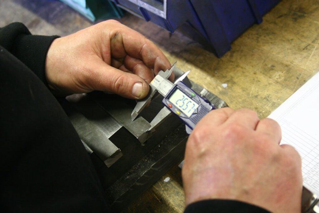
Traditional hand tools have clear limitations when dealing with heavy industrial machinery. A technician using calipers and micrometers might capture 10 or 20 discrete dimensions. If a housing has complex internal draft angles or organic curves, manual measurement cannot capture those geometries accurately. A single human error in reading a micrometer can ruin an entire machining run.
A professional reverse engineering 3D scanner eliminates these blind spots. For instance, the Peel 3.CAD system scans at a rate of 1,250,000 measurements per second. It collects a dense cloud of millions of data points across the entire surface of the part, leaving no feature unmeasured. This speed and density allow us to capture a complete component in minutes rather than spending days drafting manual sketches.
Hybrid Modeling and Design Intent
Reconstructing an industrial part requires a balance between two different modeling philosophies: design intent and as-built modeling. Design intent modeling means normalizing the measurements to their original, intended dimensions. If the scanner measures a worn bore at 99.92 mm, but the design logic indicates it was originally a standard 100.00 mm bore, we model it as 100.00 mm.
As-built modeling, on the other hand, captures the part exactly as it exists in the physical world, complete with warpage, wear, and manufacturing defects. This is crucial when we need to design a custom mating bracket that fits perfectly onto an old, distorted gearbox housing.
Hybrid modeling allows us to combine both approaches. We use parametric modeling to define the standard geometric features, such as cylinders, planes, and bolt patterns, while using freeform organic surfaces to capture complex cast shapes. Real-time deviation analysis then compares our CAD model back to the original scan mesh, highlighting any areas that fall outside our specified tolerances.
Step-by-Step Scan-to-CAD Workflow for Industrial Components
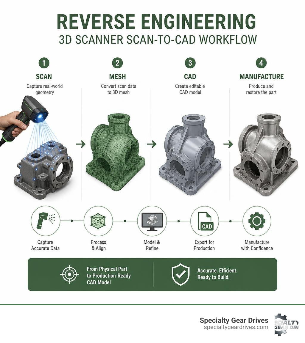
Recreating a physical part digitally requires a structured, step-by-step process.
- Preparation and Scanning: We clean the part and apply a temporary, matte scanning spray if the surface is highly reflective or dark. We then scan the object from multiple angles to capture all visible surfaces.
- Mesh Generation: The raw point cloud data is processed and converted into a watertight polygon mesh, typically in STL, OBJ, or PLY format.
- Alignment: We align the mesh to a logical coordinate system, establishing primary datums and reference planes using the 3-2-1 alignment method.
- Feature Extraction: We extract geometric primitives like cylinders, planes, and cones, and sketch cross-sections through the mesh to build the CAD model.
- Accuracy Verification: We run a deviation analysis to compare the new CAD model against the scan data, ensuring all features are within tolerance before exporting.
This structured workflow is essential when restoring worn components. For example, when repairing a heavy drive shaft, we often combine welding and machining. The details in The Art of the Weld: How to Build Up and Repair Worn Shafts outline how we build up these surfaces.
After welding, we scan the shaft to verify that we have added enough material before we begin line boring. This process is further detailed in Bore No More: How Housing Line Boring Repairs Heavy Equipment, which shows how we restore worn bearing bores to their original alignment using precision machining guided by digital data.
Hardware and System Requirements for 3D Scanning
Processing raw scan data requires significant computing power. A single scan of a large gearbox housing can easily contain tens of millions of polygons, which will overwhelm standard office computers.
To handle these massive datasets efficiently, your workstation should meet the following specifications:
- Operating System: Windows 10 or 11 (64-bit is required to address large memory pools)
- Processor: Intel Core i7 or i9, or AMD Ryzen 7 or 9 (high single-core clock speeds are critical for CAD processing)
- System Memory (RAM): 32GB minimum, though 64GB is highly recommended for handling meshes over 50 million triangles
- Graphics Card (GPU): Dedicated NVIDIA RTX series card with at least 8GB of VRAM to handle real-time rendering and deviation maps
- Storage: Fast NVMe SSD for quick file loading and caching
Converting Scan Data to Production-Grade CAD
The transition from a raw polygon mesh to a production-grade CAD model requires software that can generate clean, mathematically defined geometry. Standard STL files are made of millions of flat triangles, which CNC milling machines and lathes cannot use directly for precision machining.
To create true parametric models, we use software powered by industrial geometry engines, such as the Siemens Parasolid kernel found in QUICKSURFACE Pro. This engine allows us to export clean STEP or IGES files that contain exact mathematical definitions of cylinders, planes, and NURBS (Non-Uniform Rational B-Splines) surfaces. These formats are universally accepted by all major CAD and CAM packages, ensuring the machinist receives perfect geometry.

Top Software Tools for Scan-to-CAD Conversion
Selecting the right software is just as important as choosing the scanner hardware. Different platforms cater to different budgets, accuracy requirements, and user skill levels.
| Software | Primary Advantage | Mesh Capacity | Best Suited For |
|---|---|---|---|
| QUICKSURFACE Pro | Extremely fast learning curve, powerful hybrid modeling | ~100 million triangles | Dedicated scan-to-CAD workflows |
| Peel.CAD | Affordable, direct bridge to standard CAD tools | Moderate | Simple entity extraction and alignment |
| EXModel | Direct mesh-to-parametric conversion | High | Quick geometric reconstruction |
| ZEISS Reverse Engineering | Highly precise metrology and surface approximation | Unlimited | Aerospace and tight-tolerance heavy industry |
Standalone and Plugin Software Options
Engineers can choose between standalone reverse engineering platforms and plugins that integrate directly into existing CAD software. Standalone platforms like QUICKSURFACE Pro or ZEISS offer specialized, highly optimized tools designed specifically for handling heavy mesh data without slowing down.
Alternatively, plugins like QUICKSURFACE for SOLIDWORKS or Mesh2Surface for Rhino allow you to work within the CAD environment you already know. This eliminates the need to learn a completely new interface. Plugins are often more cost-effective for teams that only perform reverse engineering occasionally, while standalone platforms offer maximum speed and tool depth for dedicated reconstruction work.
Choosing the Right Reverse Engineering 3D Scanner Software
When selecting your software, consider the licensing structure and the ongoing costs. Some platforms are sold as permanent licenses with optional yearly maintenance fees, which usually run around 10% of the initial purchase price. Others require annual subscriptions.
The learning curve is another critical factor. While some high-end metrology suites can take months of training to master, tools like QUICKSURFACE are designed to make users productive in days rather than months. Most reputable software providers offer 30-day free trials, allowing you to test the workflow on your own industrial parts before making a commitment.
Frequently Asked Questions About 3D Scan-to-CAD
How accurate is a reverse engineering 3D scanner for industrial parts?
Professional-grade 3D scanners achieve high accuracy levels suitable for demanding industrial applications. For example, the Peel 3.CAD system provides a physical accuracy of up to 0.050 mm, with a volumetric accuracy of 0.050 mm plus an additional 0.100 mm per meter of object length.
To maintain this level of precision, scanners must be calibrated regularly using certified calibration plates, especially when moving between different temperature environments in a rebuild shop.
Can a 3D scanner directly output a STEP or IGES CAD file?
No, 3D scanners cannot directly output STEP or IGES files. Scanners capture physical surfaces as point clouds, which are then converted into polygon meshes (usually STL or OBJ files).
To get a parametric STEP or IGES file, you must use bridge software like Peel.CAD or QUICKSURFACE to extract the geometric shapes and export them as mathematical CAD entities.
What is the difference between design-intent and as-built modeling?
Design-intent modeling reconstructs the part as it was originally designed, correcting for any physical wear, casting defects, or manufacturing variations.
As-built modeling captures the exact physical shape of the object as it exists right now, including any warping, twisting, or wear. This is necessary when you must manufacture a new component that has to mate perfectly with a distorted, older machine.
Conclusion
A reverse engineering 3D scanner is an indispensable tool for keeping heavy industrial operations running when original drawings are lost to time. By converting physical parts into highly accurate, editable CAD models, we can manufacture replacement gears, rebuild damaged housings, and restore worn shafts with absolute confidence.
At Specialty Gear Drives, based in Largo, Florida, we specialize in repairing and rebuilding industrial gearboxes for heavy industries across Florida, Georgia, Alabama, Mississippi, South Carolina, and Louisiana. We understand that a failed speed reducer or drive system can halt your entire production line. That is why we offer 24–48 hour emergency service, free pickup and delivery, and a comprehensive 24-month warranty on our work.
By utilizing advanced engineering techniques, we can deliver up to 60% savings compared to the cost of buying a brand-new OEM gearbox. If you have a worn, damaged, or obsolete gearbox that needs to be restored to OEM specifications, contact us today through our Industrial Gearbox Repair page to get your equipment back in service quickly.