The Ins and Outs of 3D Laser Scanner Reverse Engineering
When a Gearbox Has No Blueprint, 3D Laser Scanning Fills the Gap
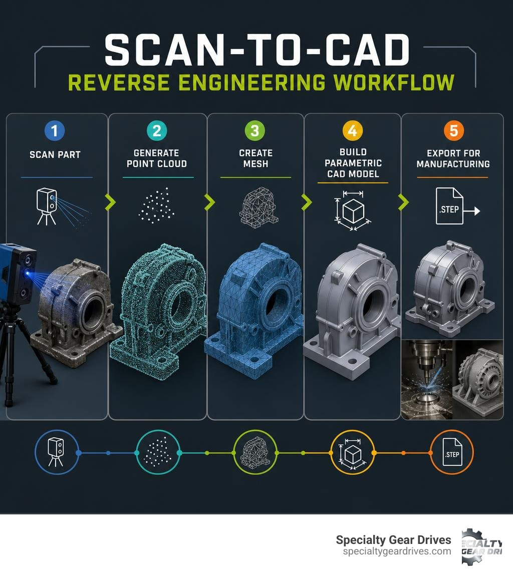
3D laser scanner reverse engineering is the process of using a laser-based scanner to capture the exact geometry of a physical part, then converting that data into a usable CAD model, without relying on original drawings or OEM documentation. Here’s the short version of how it works:
- Scan the physical component with a 3D laser scanner to capture millions of surface points
- Generate a mesh from the resulting point cloud data
- Convert the mesh into a parametric CAD model using reverse engineering software
- Export the CAD file for machining, fabrication, or further engineering analysis
For plant managers and maintenance engineers, that process matters most when a critical gearbox fails and the OEM drawings simply don’t exist, or the manufacturer has been out of business for decades.
That’s a more common situation than most people admit. A large portion of the industrial equipment running in processing plants, mining operations, and conveyor systems today has no accessible digital documentation. When a gear housing cracks or a shaft journal wears beyond tolerance, traditional measurement tools like calipers or coordinate measuring machines (CMMs) can only capture so much. Complex contoured surfaces, tight internal features, and worn geometry push those tools to their limits.
3D laser scanning changes the equation. A modern scanner can capture tens of millions of surface points per second, producing a complete digital record of the part as it actually exists, not as it was originally designed. Companies using 3D scanning in their reverse engineering workflows have reported time and cost savings of up to 85% compared to traditional methods.
For a mining operation where a stopped conveyor costs thousands of dollars per hour, that kind of speed isn’t a nice-to-have.
What is 3D Laser Scanner Reverse Engineering?
3D laser scanner reverse engineering is the digital reconstruction of a physical object into a three-dimensional CAD model using optical laser measurement. We use this method to capture the exact physical geometry of worn or obsolete gearbox components, allowing us to manufacture precise replacement parts when original drawings are missing. The process bridges the gap between physical machinery and modern digital manufacturing.
By projecting laser lines onto a surface and recording the reflection with high-resolution cameras, the scanner calculates the precise coordinates of millions of points. This collection of points is called a point cloud. In industrial repair, we transform this raw point cloud into a clean polygon mesh, which then serves as a template to build a parametric CAD model.
This approach is invaluable when you need to find a fast solution for an out-of-production speed reducer. Instead of guessing critical dimensions or waiting weeks for an OEM response, we scan the existing parts to recreate the original design intent. You can learn more about finding local repair solutions in our guide on how to Don’t Grind Your Gears and Find the Best Gearbox Repairing Near Me.
Traditional CMM vs. 3D Laser Scanner Reverse Engineering
Coordinate measuring machines (CMMs) measure physical parts using a contact probe that physically touches the surface of the component at discrete points. 3D laser scanners capture the entire surface of the part without physical contact, gathering millions of points in seconds. While a CMM is highly accurate for simple geometric features, it is slow and cannot efficiently capture complex, organic surfaces.
A CMM requires a skilled operator to manually program or guide a physical probe to touch a few hundred points over several hours. In contrast, a metrology-grade 3D laser scanner can capture up to 35 million points per second. This speed makes laser scanners up to nine times faster than a traditional CMM for standard industrial parts.
| Feature | Contact Probing (CMM) | 3D Laser Scanning |
|---|---|---|
| Measurement Method | Physical contact probe | Non-contact optical laser |
| Data Capture Speed | Hours for a few hundred points | Seconds for millions of points |
| Surface Coverage | Limited to touched points | 100 percent surface coverage |
| Accuracy | Up to 2 microns (0.002 mm) | Up to 20 to 50 microns (0.02 to 0.05 mm) |
| Complex Geometries | Extremely difficult or impossible | Highly efficient and detailed |
| Portability | Generally fixed in a metrology lab | Highly portable for field use |
While a CMM still holds an advantage in raw single-point accuracy for tight machining tolerances, modern metrology-grade laser scanners offer accuracy levels down to 20 microns. This is more than precise enough for the vast majority of industrial gearbox housings, shafts, and large gear profiles.
Design Intent vs. As-Built Modeling in Industrial Repairs
Design intent modeling reconstructs a part to its original, ideal dimensions before wear or damage occurred, while as-built modeling captures the part exactly as it exists right now, including any wear, deformation, or casting imperfections. Choosing the right modeling strategy is critical for successful industrial repairs.
When we reverse engineer a worn helical gear, we use design intent modeling. We analyze the scanned data to determine the original pitch, pressure angle, and tooth profile, stripping away the wear and tear. This allows us to manufacture a brand-new gear that matches the original design specifications.
Conversely, as-built modeling is necessary when we need to match a replacement part to a distorted or repaired mating component. For example, if a heavy gearbox housing has undergone extensive structural repair, we must model the housing exactly as it sits. This ensures that any line boring or shaft installation aligns perfectly with the current state of the machinery. You can read more about restoring damaged housings in our article on How Gearbox Housing Welding Services Restore Damaged Castings.
Key Benefits of 3D Scanning for Heavy Machinery
Using 3D scanning to reverse engineer heavy machinery parts reduces production lead times, cuts manufacturing costs, and eliminates manual measurement errors. This technology allows us to bypass the slow, traditional process of drafting parts by hand with calipers and micrometers.
The global 3D metrology market is projected to grow from $10.6 billion in 2022 to $15.9 billion by 2027, with reverse engineering serving as a primary driver. This growth is fueled by the massive efficiency gains realized across industrial sectors. By capturing complete surface data in minutes, we can reduce the development process of analyzing data and validating designs by up to 80 percent.

This efficiency is especially beneficial when dealing with large, heavy components like industrial gearboxes, where manual measurement is physically challenging and prone to human error. For example, when restoring worn bores in large housings, laser scanning provides the precise data required for line boring operations. Learn more about this process in our guide on how Bore No More: How Housing Line Boring Repairs Heavy Equipment.
Minimizing Downtime with 3D Laser Scanner Reverse Engineering
The fastest way to reduce unplanned downtime during a gearbox failure is to scan the damaged components directly on-site or in our Largo shop to begin the remanufacturing process immediately. When a critical drive system fails in a paper mill or chemical plant, every hour of lost production costs thousands of dollars.
Traditional reverse engineering of a complex gear set can take days of manual sketching, modeling, and physical verification. With a portable 3D laser scanner, we can capture the entire geometry of a broken shaft or gear in less than an hour. The scan data is immediately sent to our engineering team to begin modeling the replacement.
This rapid data acquisition means we can start machining new components while the failed gearbox is still being disassembled. Integrating this technology with proactive maintenance strategies keeps your plant running smoothly. Read more about protecting your assets in our article on How Gearbox Condition Monitoring Saves Your Machinery and Your Sanity.
The Step-by-Step Scan-to-CAD Workflow
The scan-to-CAD workflow translates physical geometry into a functional digital blueprint through a structured sequence of data capture, processing, and parametric modeling.
The workflow consists of four main phases:
- Preparation and Scanning: Cleaning the part and capturing its geometry with a 3D laser scanner.
- Mesh Processing: Aligning scans, filtering noise, and creating a clean STL polygon mesh.
- Parametric Modeling: Using the mesh as a visual template to build solid CAD features (primitives, extrusions, and sweeps).
- Validation and Export: Comparing the CAD model back to the scan data to verify accuracy before exporting to STEP or IGES formats.
This structured workflow ensures that the final CAD model is not just a dumb surface representation, but a fully editable parametric model that can be used for CNC machining or structural analysis.
Preparing and Scanning the Physical Component
Successful 3D scanning requires preparing the component surface to ensure the laser light reflects correctly back to the scanner sensors. Optical scanners struggle with highly reflective, dark, or translucent surfaces.
To prepare a part, we clean away all grease, oil, and heavy rust. For shiny machined surfaces like shaft journals or polished gear teeth, we apply a very thin, temporary matte spray. This micro-thin powder coating creates a dull, opaque surface that allows the laser to capture clean data without distorting the measurements.
Next, we place small, highly reflective target markers on or around the part. These targets act as reference points, helping the scanner software stitch multiple scans together as we move around the object. This is particularly important for large components where we must maintain line of sight around complex physical features. This level of precision is critical when preparing parts for repair. For more on shaft preparation, see our guide on The Art of the Weld: How to Build Up and Repair Worn Shafts.
Processing Point Clouds and Creating Parametric CAD Models
Point cloud processing converts raw coordinates into a clean polygon mesh that serves as the foundation for building a parametric CAD model. The raw scan data often contains millions of individual points that must be filtered and aligned.
We import the raw point cloud into specialized software like Geomagic Design X or ZEISS Reverse Engineering. The software filters out background noise, aligns the scans using the target markers, and connects the points to form a polygon mesh. This mesh is typically saved as an STL file.
While an STL mesh is useful for 3D printing, it is not an editable CAD model. To create a parametric CAD model, we use the mesh as a reference skeleton. We fit geometric primitives (like cylinders for shafts and planes for housing faces) directly to the mesh data. We then sketch 2D profiles on these planes and extrude or revolve them to build a solid, feature-based 3D model. This ensures the final model is fully parametric and ready for the machine shop.
Frequently Asked Questions About Industrial 3D Scanning
What types of industrial parts are hardest to scan?
Parts with deep internal cavities, narrow bores, or highly reflective surfaces are the most challenging to scan. Because 3D laser scanners rely on optical line of sight, they cannot capture surfaces that the laser light cannot reach. Deep internal oil passages, internal splines, and recessed bolt holes often require a hybrid approach, combining laser scanning for external features with physical contact probing for internal dimensions.
How accurate is 3D laser scanning for heavy gearboxes?
Modern metrology-grade 3D scanners can achieve single-point accuracy of up to 20 microns (0.02 mm) and volumetric accuracy of 0.05 mm per meter. This level of precision is more than adequate for heavy industrial gearbox housings, mounting bases, and large gear profiles. For extremely tight tolerances, such as bearing journals or high-speed gear meshes, we combine laser scanning with physical micrometers to verify critical dimensions to the thousandth of an inch.
Can you reverse engineer worn or broken components?
Yes, we can reverse engineer heavily worn, chipped, or broken components by applying design intent modeling. If a gear has several broken teeth, we scan the remaining intact teeth to determine the exact tooth profile, module, and pressure angle. We then use CAD software to reconstruct the missing teeth symmetrically around the gear blank, restoring the component to its original, un-failed specifications.
Conclusion
At Specialty Gear Drives, we utilize 3D laser scanner reverse engineering to deliver fast, highly accurate repairs for industrial gearboxes across the Southeast. By combining advanced metrology with our decades of machining expertise, we help plants in Florida, Georgia, Alabama, South Carolina, Mississippi, and Louisiana avoid the high costs and long lead times of OEM replacements.
Whether you need to rebuild a massive speed reducer for a cement plant or reverse engineer a discontinued gear set for a chemical facility, our team has the tools and experience to get your operations back online quickly. We back all of our work with a 24-month warranty, offer 24 to 48-hour emergency services, and provide free pickup and delivery throughout our service states.
Do not let missing blueprints or high shipping costs slow down your operation. Learn more about our regional transport solutions in Don’t Let Shipping Costs Grind Your Gears.
If you are facing an unexpected equipment failure or need to recreate a critical obsolete component, contact us today at https://specialtygeardrives.com/industrial-gearbox-repair/ to speak with an engineering expert.