Local Gearbox Vibration Analysis Services in Alabama: A Guide
Why Gearbox Vibration Analysis in Alabama Matters for Industrial Operations
Gearbox vibration analysis in Alabama is a non-invasive condition monitoring technique that measures vibration signals from rotating gearbox components to detect developing faults before they cause unplanned downtime. Here is what Alabama plant managers need to know upfront:
- What it detects: gear tooth wear, bearing defects (BPFO, BPFI, BSF, FTF), misalignment, mechanical looseness, imbalance, and bent shafts
- How it works: accelerometers capture vibration waveforms, which are converted via Fast Fourier Transform (FFT) into frequency spectra that map directly to specific fault signatures
- Who needs it: any Alabama facility running conveyors, mixers, mills, fans, pumps, or processing lines with gearbox-driven equipment
- When to use it: as a continuous or scheduled program, not just after a fault appears
- The payoff: catching a developing gear fault early means the difference between a planned rebuild and a catastrophic failure that halts your entire production line
A single gearbox failure can result in up to 60 days of annual downtime, and the average major repair intervention runs roughly 256 hours. Alabama’s heavy industrial base, from steel mills and pulp and paper plants to chemical processing and mining operations, runs on gearbox-driven equipment that simply cannot afford unplanned stops.
The core idea is straightforward. All machinery produces vibration during normal operation. When internal components begin to wear or fail, the pattern of those vibrations changes in measurable, identifiable ways. A trained analyst, or an automated monitoring system, reads those changes the same way a doctor reads an abnormal heart rhythm.
I’m Peter Clark, and in this guide I’ll walk you through exactly how to set up and run a gearbox vibration analysis program for your Alabama facility, from sensor placement to fault diagnosis to knowing when to call in a specialist.
What is Gearbox Vibration Analysis and How It Works
Vibration monitoring is a predictive, nondestructive testing science. It identifies precursors to machine failure by plotting and analyzing vibrational waveforms. In a healthy industrial gearbox, rotating shafts, meshing gears, and rolling-element bearings generate a distinct, repeatable vibration pattern.
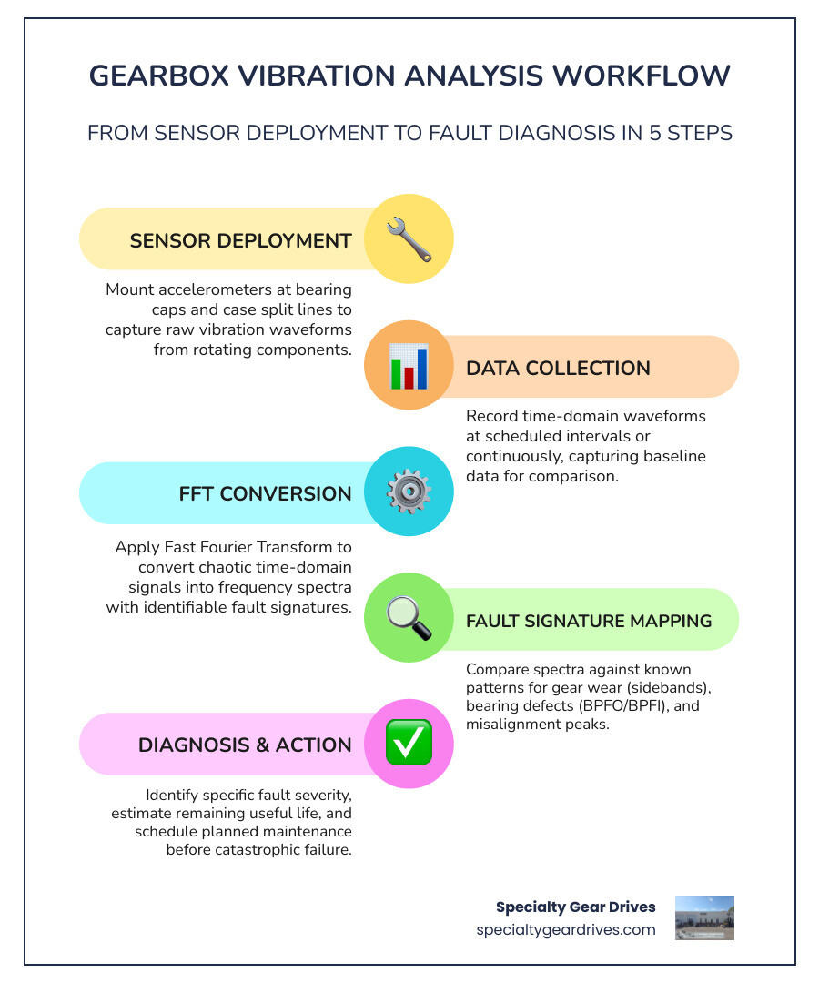
When we collect raw vibration data, the sensor records a time-domain waveform, which plots amplitude over time. Because a gearbox contains multiple shafts rotating at different speeds, this raw waveform is a chaotic mixture of overlapping signals. To make sense of it, we use a mathematical algorithm called the Fast Fourier Transform.
The Fast Fourier Transform processes the time-domain signal and converts it into a frequency-domain spectrum. This spectrum breaks down the complex wave into its individual frequency components. By analyzing the amplitude (the severity of the vibration) at specific frequencies, we isolate the mechanical source of the abnormality. This diagnostic precision is how we determine whether a vibration is caused by a worn bearing, a chipped gear tooth, or structural looseness.
Implementing this type of systematic tracking is the foundation of modern predictive maintenance. It allows us to transition away from arbitrary calendar-based maintenance schedules. To understand how these principles save resources, you can read about how gearbox condition monitoring saves your machinery and your sanity on our blog.
The Physics of Gear Mesh Frequencies
Analyzing a gearbox requires calculating the Gear Mesh Frequency. This is the rate at which mating gear teeth contact one another. It is calculated by multiplying the number of teeth on a gear by the rotational speed of its shaft:
$$\text{GMF} = \frac{\text{Number of Teeth} \times \text{Shaft RPM}}{60}$$
A gearbox vibration spectrum is dominated by the GMF and its harmonics (2x GMF, 3x GMF). In a perfectly healthy gear set, some vibration at the GMF is normal due to the physical engagement of the teeth. However, as the teeth wear, pit, or chip, the energy at these frequencies increases.
Because gearboxes generate high-frequency vibrations when teeth mesh, we must use contact sensors, specifically accelerometers, that can capture a wide frequency range. Standard noncontact proximity probes are often inadequate for monitoring gear mesh because they lack the high-frequency sensitivity required to measure up to the third harmonic of the GMF. High-quality accelerometers ensure we capture these critical high-frequency signals.
How to Set Up Gearbox Vibration Analysis Alabama Programs
Establishing a successful program in your Alabama plant starts with collecting baseline data. We cannot accurately identify an abnormal vibration unless we know what the gearbox looks like when it is running in a healthy state. This baseline must be recorded under normal operating conditions, noting the specific rotational speed, load, and temperature of the system.
Once we establish this baseline, we compare all subsequent readings against it. If you suspect your machinery is already showing signs of distress, reviewing everything you need to know about gearbox repair will help you evaluate your options before a minor anomaly becomes a major failure.
Sensor Deployment and Mounting Best Practices
Sensor placement dictates the quality of your diagnostic data. Accelerometers must be mounted as close to the internal bearings as possible. The primary mounting locations are the gear shaft bearing caps and the case split line flange.
Avoid mounting sensors on the top covers of horizontal gearboxes. These covers are often thin and prone to generating drumhead frequencies, which are local structural resonances that mask the actual vibration of the shafts and gears.
We utilize rugged, industrial-grade accelerometers (such as Wilcoxon or CTC sensors) for permanent or route-based monitoring. For journal bearings, eddy current proximity probes are used instead of accelerometers because they measure the physical displacement of the shaft relative to the bearing housing rather than the casing acceleration. When mounting accelerometers, ensuring a rigid, flat connection to the metal casing is critical. Poor coupling reduces the sensor’s mounting resonance, which filters out the high-frequency vibrations of early-stage gear and bearing defects.
Data Collection and Fault-Signature Mapping
Real-world industrial gearboxes do not run at a perfectly constant speed. Minor torque variations cause the rotational speed to fluctuate. In standard Fourier transform analysis, these slight speed variations cause spectral smearing. This means the energy of the gear mesh spreads across multiple frequency bins, making it difficult to spot subtle fault indicators.
To prevent spectral smearing, we use Time Synchronous Averaging and digital domain resampling. This technique synchronizes the vibration data acquisition with a tachometer signal, resampling the data relative to the physical rotation angle of the shaft rather than constant time intervals. This aligns each shaft order perfectly with a single frequency bin, filtering out non-synchronous background noise.
For rolling-element bearings, we rely on envelope analysis. Bearing defects produce very brief, high-frequency impacts that are easily drowned out by the heavy, low-frequency vibrations of the gears. Envelope analysis filters out the low-frequency signals and extracts the repetition rate of these impacts, allowing us to map them directly to specific bearing fault frequencies.
Identifying Common Faults with Gearbox Vibration Analysis Alabama

When an anomaly is detected, we map the frequency peaks against known fault signatures. If the analysis points to a misalignment between the motor and the gearbox, corrective action must be taken immediately. For detailed instructions on correcting this specific issue, refer to our guide on how to master gearbox laser alignment in 5 steps.
Detecting Gear Tooth Wear via Gearbox Vibration Analysis Alabama
Gear tooth wear, pitting, and cracking manifest as sideband patterns in the vibration spectrum. Sidebands are peaks that appear on either side of the Gear Mesh Frequency, spaced at intervals equal to the rotational speed of the input or output shaft.
As a gear tooth degrades, it modulates the GMF signal. For example, if an input shaft runs at 20 Hz and meshes at 1000 Hz, a cracked tooth on that shaft will produce sidebands at 980 Hz and 1020 Hz.
When a tooth is completely broken or missing, the raw time-domain waveform shows a distinct, cyclical impact once per shaft revolution. Interestingly, during severe tooth loss, statistical parameters like Root Mean Square and variance can sometimes paradoxically decrease. This occurs because the physical gap left by the missing tooth increases the damping effect as the mating teeth temporarily lose contact, demonstrating why relying purely on overall vibration levels without looking at the frequency spectrum is a major diagnostic error.
Bearing Defects and Mechanical Looseness
Rolling-element bearings produce highly specific fault frequencies based on their internal geometry. These are categorized into four distinct signatures:
- BPFO (Ball Pass Frequency Outer Race): Indicates a defect on the outer raceway.
- BPFI (Ball Pass Frequency Inner Race): Indicates a defect on the inner raceway.
- BSF (Ball Spin Frequency): Indicates a defect on the rolling elements themselves.
- FTF (Fundamental Train Frequency): Indicates a defect or looseness in the bearing cage.
Mechanical looseness is identified by a long string of harmonics of the shaft running speed (1x, 2x, 3x, 4x, etc.). Unbalance typically presents as a dominant, clean peak at exactly 1x the shaft rotational speed in the radial direction. A bent shaft or severe angular misalignment produces high axial vibration, typically dominant at 1x and 2x the running speed.
Industrial Applications for Vibration Monitoring in Alabama
Alabama’s industrial sectors rely on heavy-duty gearboxes that operate under extreme loads, high temperatures, and abrasive environments.
In pulp and paper mills, massive paper machine dryer sections and repulper drives run continuously. A failure here halts the entire line. Vibration monitoring in these plants focuses on detecting early bearing wear caused by water contamination in the oil.
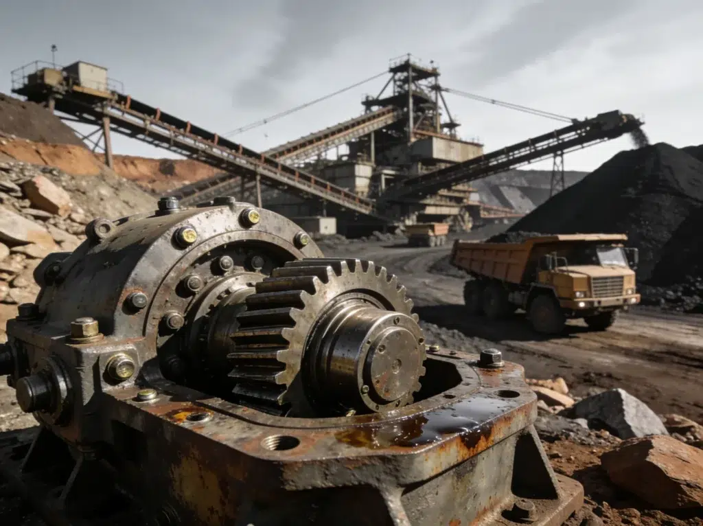
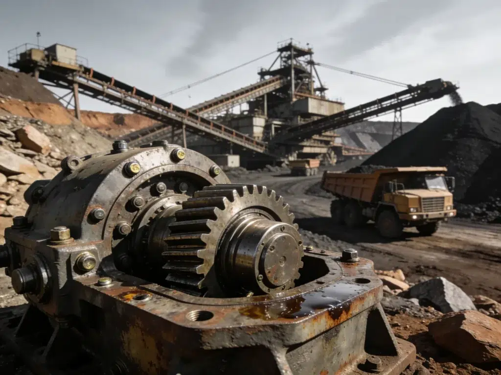
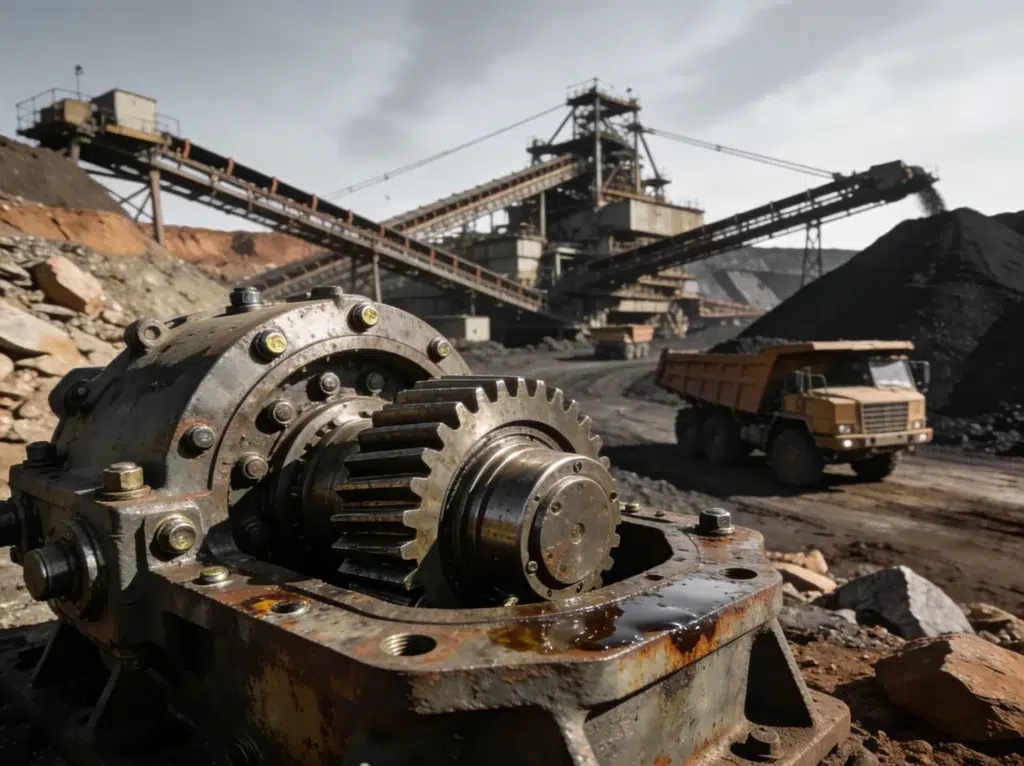
In coal and aggregate mining operations, conveyor drives, crushers, and stacker-reclaimers are subjected to shock loading and heavy dust, making misalignment and housing looseness common issues.
For steel mills, the primary concern is the extreme torsional stress placed on gear drives during rolling operations.
In chemical processing plants, cooling tower gearboxes are highly susceptible to shaft misalignment due to structural shifting of the tower frame over time.
The table below outlines typical vibration velocity limits across these industries based on ISO and AGMA guidelines for in-service machinery:
| Industry | Primary Equipment | Typical Alert Limit (mm/s RMS) | Critical Action Limit (mm/s RMS) | Primary Failure Mode |
|---|---|---|---|---|
| Pulp & Paper | Paper Machine Dryers, Repulpers | 2.8 | 4.5 | Bearing wear, water contamination |
| Mining | Conveyor Drives, Crushers | 4.5 | 7.1 | Misalignment, housing looseness |
| Steel Mills | Roll Table Drives, Pinion Stands | 4.5 | 7.1 | Gear tooth fatigue, shock cracks |
| Chemical | Cooling Tower Fans, Mixers | 2.8 | 4.5 | Shaft misalignment, unbalanced fans |
| Cement | Rotary Kiln Drives, Ball Mills | 4.5 | 7.1 | Girth gear wear, pinion misalignment |
Frequently Asked Questions about Gearbox Vibration Analysis
When establishing a predictive maintenance program, technical teams often raise questions regarding the limits of the technology and how to structure their diagnostics. If you are trying to determine whether your machinery has progressed past the point of monitoring and requires immediate professional intervention, our article on industrial gearbox repair florida 7 signs you need a pro provides a practical checklist.
Overcoming Low-Speed Limits in Gearbox Vibration Analysis Alabama
Low-speed gearboxes, specifically those rotating below 10 RPM, present a significant challenge for standard vibration analysis. Because the kinetic energy generated by low-speed impacts is very low, the resulting vibration signals are often buried in background electronic noise.
To overcome this limit, we utilize high-frequency envelope analysis and specialized low-frequency accelerometers with high sensitivity (typically 500 mV/g or 1000 mV/g instead of the standard 100 mV/g). Advanced signal processing techniques, such as I-DNA (Intelligent Demodulation Noise Analysis), allow for the detection of bearing faults down to 1 RPM by isolating and amplifying micro-shocks within the high-frequency spectrum.
How does vibration analysis integrate with other predictive maintenance tools?
Vibration analysis is highly effective, but it should not be used in isolation. A comprehensive program integrates multiple technologies:
- Oil Analysis: Detects the physical presence of wear debris, additive depletion, and chemical contamination (such as water or process chemicals) before the physical wear is severe enough to cause measurable vibration.
- Thermography: Identifies localized hot spots caused by poor lubrication, excessive friction, or overloaded gear meshes.
- Motor Current Signature Analysis (MCSA): Helps determine if a vibration is originating from the gearbox or from electrical defects in the driving motor, such as cracked rotor bars. MCSA detects rotor bar issues by identifying slip-frequency sidebands around the line frequency, which often mimic mechanical gearbox faults under load.
- Passive Ultrasonic Listening: Captures early-stage bearing turbulence and pressure leaks in the 20 kHz to 100 kHz range, long before traditional vibration sensors register a change.
What certifications should a vibration analyst hold?
Interpreting complex gearbox vibration spectra requires formal training. You should look for analysts certified under ISO 18436-2, which defines the standard for vibration analysis personnel.
- Category II: Qualified to collect data, perform basic diagnostics, and establish baselines.
- Category III: Qualified to design monitoring programs, perform advanced spectral analysis, diagnose complex multi-shaft gearboxes, and recommend corrective actions.
Analysts may also hold certifications from the American Society for Nondestructive Testing (ASNT).
Conclusion
When gearbox vibration analysis identifies a critical fault, the next step is executing a high-quality repair. At Specialty Gear Drives, we repair and rebuild industrial gearboxes for heavy industries across Alabama, Georgia, South Carolina, Mississippi, Louisiana, and Florida.
We do not perform on-site field repairs. Instead, we operate an advanced, fully equipped rebuild facility in Largo, Florida, where all line boring, gear manufacturing, and gearbox rebuilding are performed in-house. To make this process as straightforward as possible for Alabama plants, we provide free pickup and delivery. We will dispatch a transport team directly to your facility, haul the damaged unit to our shop, perform the complete rebuild, and return it to your site.
Our key advantages include:
- Rapid Shop Turnaround: 24 to 48 hour emergency repair turnaround to minimize your downtime.
- Significant Savings: Rebuilding your existing unit provides up to 60% savings compared to the cost of purchasing a brand-new gearbox.
- Unmatched Warranty: Every rebuild is backed by our comprehensive 24-month warranty.
If you have a gearbox showing elevated vibration levels, do not wait for a catastrophic failure to occur. Contact us today at Specialty Gear Drives to schedule a free pickup and get your critical equipment restored to OEM specifications.