How to Master Gearbox Laser Alignment in 5 Steps
Why Shaft Misalignment Is Silently Destroying Your Gearboxes
Gearbox laser alignment is the process of using precision laser sensors to position a gearbox’s input and output shafts so their centerlines are in the correct relative position, both horizontally and vertically, under real operating conditions.
If you need the short answer on how it works:
- Diagnose soft foot at all four machine feet before touching anything else.
- Mount laser sensors on the shafts on either side of the coupling.
- Measure misalignment and calculate a cold offset to account for thermal growth.
- Make corrections by shimming and adjusting the machine feet.
- Verify the result against RPM-based tolerance targets before returning to service.
The case for doing this carefully is hard to argue with. Over 50% of plant breakdowns are linked to shaft misalignment. A single failed gearbox on a conveyor line or processing system can halt an entire production shift, and the root cause often traces back to shafts that were never properly aligned in the first place.
Traditional methods like dial indicators and straight edges can get close, but they carry real limitations. Gravity affects the indicator hardware, bracket sag distorts readings, and repeating a measurement twice rarely gives you the same number. Laser systems eliminate most of those error sources and give you consistent, documented results in a fraction of the time.
Misalignment doesn’t always announce itself with an immediate failure. It shows up first as elevated vibration, accelerated bearing wear, overheated seals, and couplings that need replacing far sooner than they should. By the time a gearbox fails outright, the damage has usually been building for weeks or months.
The five steps below cover the full procedure, from pre-alignment checks through final verification, including how to handle thermal growth, soft foot, and tolerance targets by RPM.
Why Gearbox Laser Alignment Outperforms Traditional Methods
Laser alignment systems outperform traditional methods because they eliminate bracket sag, bypass human reading errors, and automatically calculate complex compensation factors like thermal growth.
When using dial indicators, the physical weight of the mounting bars causes them to bend slightly under gravity. This physical bending is known as bracket sag. Even a tiny sag of a few thousandths of an inch can throw off your calculations and result in a poor alignment. Laser beams are entirely immune to gravity and bracket sag, meaning the measurement you see on the screen is the actual state of the shafts.
Straight edges and feeler gauges are highly subjective. Two different technicians can measure the same coupling with a straight edge and come up with different readings based on their angle of view or how tightly they pull the feeler gauge. Laser systems use digital sensors that provide repeatable measurements down to a fraction of a mil.
If you want to keep your machinery running reliably, laser precision is indispensable. For more details on maintaining your rotating assets, read about How Gearbox Condition Monitoring Saves Your Machinery and Your Sanity.
The 5 Steps to Master Gearbox Laser Alignment
Achieving precision alignment requires a structured approach that starts at the machine base and ends with a verified hot run.
Skipping any of these steps will result in a phantom alignment, which is an alignment that appears correct on your tooling when the machine is cold but becomes highly misaligned once the system reaches operating temperature.
Step 1: Pre-Alignment Checks and Soft Foot Correction
Soft foot is corrected by measuring the gap under each machine foot with feeler gauges while the hold-down bolts are loose, then adding precision shims until all four feet sit perfectly flat on the foundation.
Any foot deflecting more than 0.05 millimeters (2 mils) when tightened must be corrected before you take any coupling measurements. If you attempt to align a machine with an uncorrected soft foot, tightening the bolts will distort the gearbox frame, pull the bearings out of round, and ruin your alignment readings.
There are four primary types of soft foot:
- Parallel soft foot: The foot sits parallel to the baseplate but is elevated, leaving a uniform gap underneath.
- Bent soft foot: The foot is angled relative to the baseplate, creating a wedge-shaped gap.
- Squishy soft foot: Dirt, rust, paint, or too many stacked shims create a springy, unstable base.
- Induced soft foot: External forces, such as pipe strain or coupled machinery, pull the gearbox out of position.
Always limit your shim stacks to a maximum of four shims per foot. Stacked hand-cut shims behave like springy washers under load, which introduces instability and causes your alignment to shift during final torqueing. If the gearbox housing itself is distorted, you may need more intensive repairs. Learn how housing issues are resolved in our guide on Bore No More: How Housing Line Boring Repairs Heavy Equipment.
Step 2: Mounting the Gearbox Laser Alignment System
To mount the system, attach the laser transmitter to the shaft of the driving machine and the receiver to the shaft of the driven gearbox using the provided chain clamps or magnetic brackets.
The sensors must be secure and mounted on the rotational centers of the shafts, not on the outer coupling sleeves. This ensures that the laser measures the actual centerlines of the rotating shafts, bypassing any coupling runout or surface imperfections.
Once mounted, turn on the system and adjust the laser beams so they strike the center of the receiver targets. The software will guide you through entering the physical dimensions of your machine train, including the distance between the sensors, the distance from the sensors to the coupling, and the distances to the front and rear feet of the movable machine. Accurate dimension entry is critical because the software uses these values to calculate the exact shim adjustments required at the feet.
If your shafts are worn or damaged, mounting the sensors accurately can be difficult. You can learn about restoring these surfaces in our article on The Art of the Weld: How to Build Up and Repair Worn Shafts.
Step 3: Measuring Misalignment and Calculating Thermal Growth
To measure misalignment, rotate the coupled shafts together and record readings at a minimum of three rotational positions spaced at least 30 to 40 degrees apart.
Most modern systems allow you to take measurements continuously as you rotate the shafts, which helps smooth out any minor rotational bumps.
Once the initial measurements are recorded, you must calculate and apply a cold offset to compensate for thermal growth. Industrial gearboxes and motors expand as they heat up to operating temperatures. A cast-iron gearbox housing rising 50 degrees Fahrenheit with a 15-inch shaft height will grow upward by approximately 4.4 mils.
If you align the shafts to absolute zero when they are cold, the gearbox will grow out of alignment once it reaches its operating temperature. You must use the thermal expansion coefficients of your specific materials (such as mild steel or cast iron) to calculate this growth, then program the laser system to target a specific cold offset.
Step 4: Making Precision Adjustments
Make your vertical adjustments first by adding or removing precision shims under the machine feet, then make horizontal adjustments using jack screws to nudge the machine into place.
The laser system will provide live, real-time feedback on your screen showing exactly how much shim thickness to add to each foot and which way to push the machine horizontally.
When adjusting horizontally, always leave the hold-down bolts slightly snug to prevent the machine from twisting or jumping out of position. Use jack screws to make controlled, incremental movements.
Be aware of foundation flexibility. Lightweight portable bases or weak steel structures can flex when you tighten the hold-down bolts, which will alter your final alignment readings. Always tighten the bolts in a progressive, diagonal torque sequence to distribute the clamping force evenly.
Step 5: Verifying the Final Gearbox Laser Alignment
Verify the alignment by rotating the shafts one more time to take a final set of readings, confirming that the offset and angularity values fall within your target tolerance band.
The live 3D interface on your laser alignment tool should show green checkmarks across all parameters, indicating that the shafts are co-linear under operating conditions.
Once the alignment is locked in, remove the laser sensors and targets before running the equipment. Establish a new vibration baseline at operating speed to confirm that the alignment holds and that there are no underlying mechanical issues.
If you find that the gearbox cannot be aligned due to internal gear wear or housing damage, you may need professional intervention. Find local support by reading Don’t Grind Your Gears and Find the Best Gearbox Repairing Near Me.
Understanding Alignment Tolerances and Operating Conditions
Aligning to coupling manufacturer tolerances is a common mistake that protects only the coupling while leaving the bearings, seals, and gears vulnerable to premature failure.
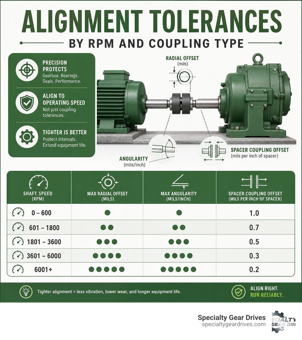
Coupling tolerances are designed to prevent the coupling elastomer or grid from tearing apart, and they are often 2 to 25 times looser than the precision shaft alignment targets required to protect your gearbox internals.
For industrial machinery, you should always align according to the operating speed (RPM) of the shaft and the coupling type. The table below outlines standard shaft alignment tolerances based on API 686 and industry best practices.
| Shaft Speed (RPM) | Max Radial Offset (Mils) | Max Angularity (Mils/Inch) | Spacer Coupling Offset (Mils per Inch of Spacer) |
|---|---|---|---|
| 900 | 6.0 | 1.0 | 1.5 |
| 1200 | 5.0 | 0.8 | 1.2 |
| 1800 | 4.0 | 0.7 | 0.9 |
| 3600 | 2.0 | 0.4 | 0.5 |
Stiff spacer couplings are highly sensitive to angular misalignment and require tighter tolerances, whereas elastomeric insert couplings are more forgiving of axial offset but still transmit high bending forces to the gearbox bearings if misaligned.
Frequently Asked Questions about Gearbox Alignment
How often should gearbox laser alignment be performed?
Gearbox laser alignment should be performed during initial commissioning, after any major maintenance or rebuild, and whenever vibration analysis indicates a spike in 1x or 2x rotational frequencies.
For critical production machinery, check the alignment annually as part of your preventive maintenance schedule. This helps catch foundation settling, baseplate deterioration, or loose hold-down bolts before they cause a catastrophic failure.
To learn more about managing these maintenance cycles and avoiding unexpected shipping delays during emergency repairs, read Industrial Gearbox Repair – Don’t Let Shipping Costs Grind Your Gears.
What are the main types of shaft misalignment?
The main types of shaft misalignment are offset (radial) misalignment, angular misalignment, axial offset, and twist misalignment.
- Offset misalignment: The shaft centerlines are parallel but do not meet at the same center point.
- Angular misalignment: The shafts meet at an angle, creating a gap that varies around the circumference of the coupling.
- Axial offset: The shafts are aligned but are spaced too far apart or too close together, putting axial thrust loads on the bearings.
- Twist misalignment: A combination of both offset and angular errors occurring across both the horizontal and vertical planes.
How does misalignment cause gearbox failure?
Misalignment forces the rotating shafts to bend slightly during every rotation, which generates high cyclic stresses that lead to shaft fatigue and cracking.
These bending forces are transmitted directly into the bearings and shaft seals. This causes the seals to wear unevenly and leak oil, while the bearings suffer from localized overloading, overheating, and rapid fatigue.
In addition, misalignment alters the gear contact patterns inside the housing, leading to uneven tooth loading, increased backlash, and accelerated gear wear.
Conclusion
Mastering gearbox laser alignment is one of the most effective ways to extend the lifespan of your industrial machinery, reduce energy consumption, and eliminate unplanned downtime. By systematically checking for soft foot, mounting your laser tools correctly, accounting for thermal growth, and aligning to strict RPM tolerances, you protect your bearings, seals, and gears from destructive stresses.
When internal wear, housing distortion, or shaft damage makes precision alignment impossible on the plant floor, you need a trusted repair partner to restore your equipment to factory specifications.
Specialty Gear Drives repairs and rebuilds industrial gearboxes for demanding industries across the Southeast, including oil and gas, pulp and paper, mining, and food processing. Based in Largo, Florida, we proudly serve plants throughout Florida, Georgia, South Carolina, Alabama, Mississippi, and Louisiana.
Our team offers 24-48 hour emergency services, free pickup and delivery, a 24-month warranty on all rebuilds, and savings of up to 60% compared to buying a brand-new gearbox. Contact us today to discuss your gearbox repair needs at Industrial Gearbox Repair.