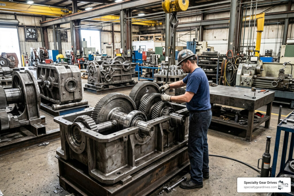
The Complete Guide to Custom Industrial Gears
Why Custom Industrial Gears Matter for Heavy Industry Operations
Custom industrial gears are precision-engineered gear components designed and manufactured to exact specifications, rather than selected from a standard catalog. When off-the-shelf gears cannot meet the torque loads, speed ratios, dimensional constraints, or environmental demands of your equipment, custom gears are the answer.
Quick answer: What are custom industrial gears?
- Designed to spec — manufactured from your drawings, CAD files, or reverse-engineered from a sample part
- Built for your application — specific tooth geometry, materials, heat treatment, and precision grades matched to your operating conditions
- Available in all major types — spur, helical, bevel, worm, internal, herringbone, and rack-and-pinion configurations
- Held to recognized standards — AGMA, ISO 1328, DIN 3961, and customer-specific quality requirements
- Used across heavy industry — mining, pulp and paper, petrochemical, food processing, cement, marine, and power transmission
A single failed gear in a conveyor drive or processing line does not just damage the gearbox. It stops production. In facilities across the Southeast, from phosphate processing plants in Florida to pulp and paper mills in Alabama and Mississippi, unplanned downtime from worn or mismatched gears costs far more than the component itself.
The global industrial gears market was valued at roughly $245 billion in 2023 and is on track to exceed $380 billion by 2032. More telling for plant engineers: over 75% of heavy machinery, automotive, and power transmission applications require custom or made-to-order gears rather than off-the-shelf parts. Standard catalog gears simply do not cover most real-world applications.
High humidity, coastal salt air along the Gulf and Atlantic, and extreme heat loads are real factors in how Southeast industrial facilities spec and maintain their drive systems. A gear that performs well in a climate-controlled environment may wear prematurely in a Louisiana petrochemical plant or a coastal Georgia paper mill. Material selection, surface treatment, and heat treatment all have to account for where the gear actually runs.
This guide covers everything you need to know about specifying, manufacturing, and sourcing custom industrial gears, from gear types and materials to manufacturing processes, quality standards, and what to expect from lead times and minimum orders.
Core Types of Custom Industrial Gears and Their Performance Impact
Selecting the right gear configuration directly dictates the mechanical efficiency, load distribution, and operational noise of your machinery. Every custom gear type utilizes unique geometry to manage torque transfer, requiring precise alignment of key design parameters.
The pitch diameter represents the imaginary circle where the teeth of two mating gears meet and roll together without slipping. This measurement determines the gear ratio and center-to-center spacing of your shafts. Another critical parameter is the pressure angle, which is the angle between the tooth face and the line of action. Standard industrial gears typically use a 14.5-degree or 20-degree pressure angle to balance tooth strength against the radial load applied to the supporting bearings. When dealing with angled teeth, the helix angle defines the angle at which the teeth are cut relative to the gear axis, directly influencing how smoothly the teeth engage.
To understand how these parameters affect your machinery, you can read our Custom Gear Manufacturing Imperial Guide 2026.
Spur and Helical Configurations for Parallel Shafts
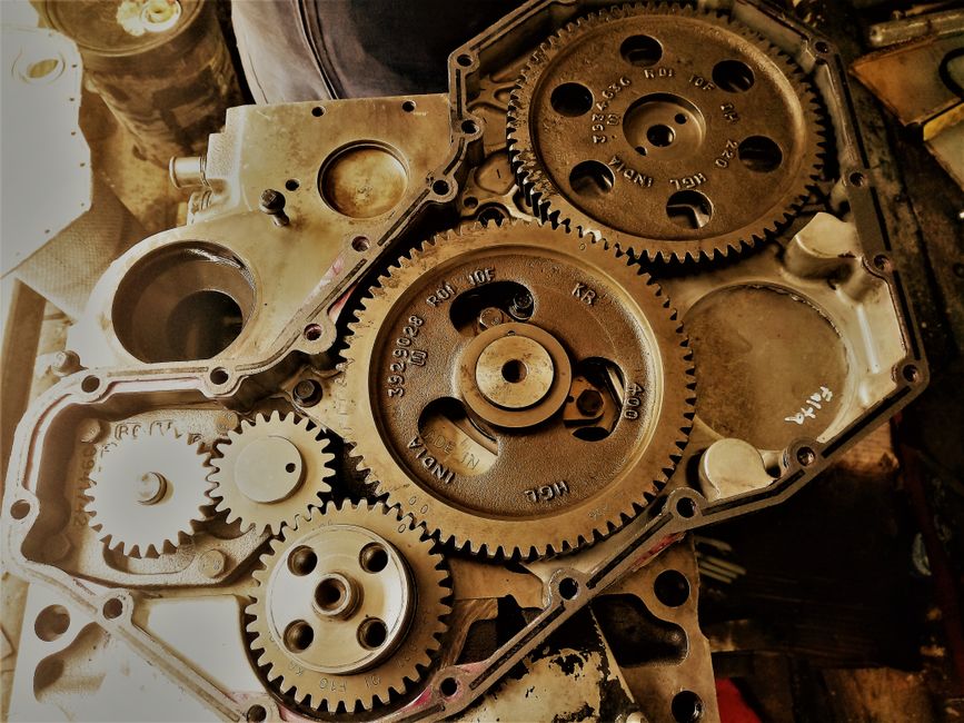
Spur gears are the simplest and most common option for transmitting power between parallel shafts. They feature straight teeth cut parallel to the shaft axis, operating at an impressive 95% to 99% mechanical efficiency. Because their teeth engage all at once across the entire face width, spur gears can produce significant noise and vibration under high-speed conditions.
Helical gears solve this noise issue by using teeth cut at an angle. This helix angle allows the teeth to engage gradually, starting at one end of the tooth and rolling smoothly to the other. The gradual engagement makes helical gears ideal for high-speed, high-load applications like heavy conveyor systems and paper mill drives.
The angled teeth of a helical gear generate axial thrust, which is a lateral force that pushes the gear along its shaft. Your system must use thrust bearings to handle this force. If you want to eliminate axial thrust entirely, herringbone gears feature two opposing sets of helical teeth cut on a single gear face, canceling out the lateral forces while retaining high load capacities.
Bevel and Worm Designs for Intersecting or Right-Angle Shafts
Bevel gears transmit power between shafts that intersect, usually at a 90-degree angle. Straight bevel gears have straight teeth and work well in low-speed applications, but they generate noise at higher velocities. Spiral bevel gears use curved, angled teeth to provide gradual tooth engagement, resulting in much quieter operation and higher torque capacity for heavy duty right-angle drives.
Worm gears use a threaded screw, called a worm, to drive a mating gear, called a worm wheel. This configuration delivers massive reduction ratios and high torque multiplication in a very compact footprint.
Worm gear sets are inherently self-locking, meaning the worm wheel cannot drive the worm backward. This safety feature is highly valuable for vertical hoists, elevators, and inclined conveyors. However, because worm gears rely on sliding friction rather than rolling contact, they generate more heat and operate at lower efficiencies than spur or helical sets.
Material Selection and Heat Treatment for Custom Industrial Gears
The life expectancy of a custom gear depends heavily on choosing the right material and heat treatment combination. Heavy machinery components must withstand high surface fatigue, bending stresses, and abrasive wear.
Standard carbon steel works well for low-load, low-speed commercial applications, but heavy industrial environments demand alloy steel grades like 8620H, 4140, or 4340. These alloys contain chromium, nickel, and molybdenum, which improve deep-hardening capabilities and impact resistance. For highly corrosive environments, such as chemical processing plants in Louisiana or coastal paper mills, stainless steel grades provide excellent protection against rust and chemical attack. Bronze is the industry standard for worm gear rims because its low coefficient of friction minimizes sliding wear against steel worms.
If your shafts are showing signs of wear alongside your gears, you can learn about restoration techniques in our guide on The Art of the Weld How to Build Up and Repair Worn Shafts.
| Material / Method | Typical Surface Hardness | Primary Advantages | Common Industrial Applications |
|---|---|---|---|
| Alloy Steel (8620H / 20CrMnTi) + Carburizing | 58–62 HRC | Maximum wear resistance, high core toughness, deep case depth | Heavy-duty spur and helical gears, mining drives |
| Medium Carbon Alloy (4140) + Induction Hardening | 50–55 HRC | Rapid processing, selective tooth hardening, minimal distortion | Large ring gears, medium-torque industrial reducers |
| Alloy Steel + Gas Nitriding | 650–750 HV | Ultra-hard surface, extremely low distortion, no post-heat-treat grinding | High-precision machinery, high-speed pinions |
| Stainless Steel (316 / 420) | Variable (Up to 50 HRC) | Exceptional corrosion resistance, food-safe characteristics | Food processing, chemical plants, marine drives |
| Phosphor Bronze | 150–200 HB | Low friction, excellent sliding wear resistance | Worm wheel rims, high-ratio speed reducers |
Carburizing is a heat treatment process that diffuses carbon into the outer layer of low-carbon alloy steel at high temperatures. Quenching then hardens this carbon-rich outer layer, creating a tough core and a wear-resistant case with a hardness of 58 to 62 HRC.
Nitriding diffuses nitrogen into the steel surface at lower temperatures, producing an ultra-hard surface layer without requiring a water or oil quench. This low-temperature process minimizes dimensional distortion, which is critical for high-precision gears. Induction hardening uses electromagnetic induction to heat only the gear teeth before rapidly quenching them, leaving the gear body in its ductile state to absorb heavy shock loads.
Precision Manufacturing Processes and Quality Standards
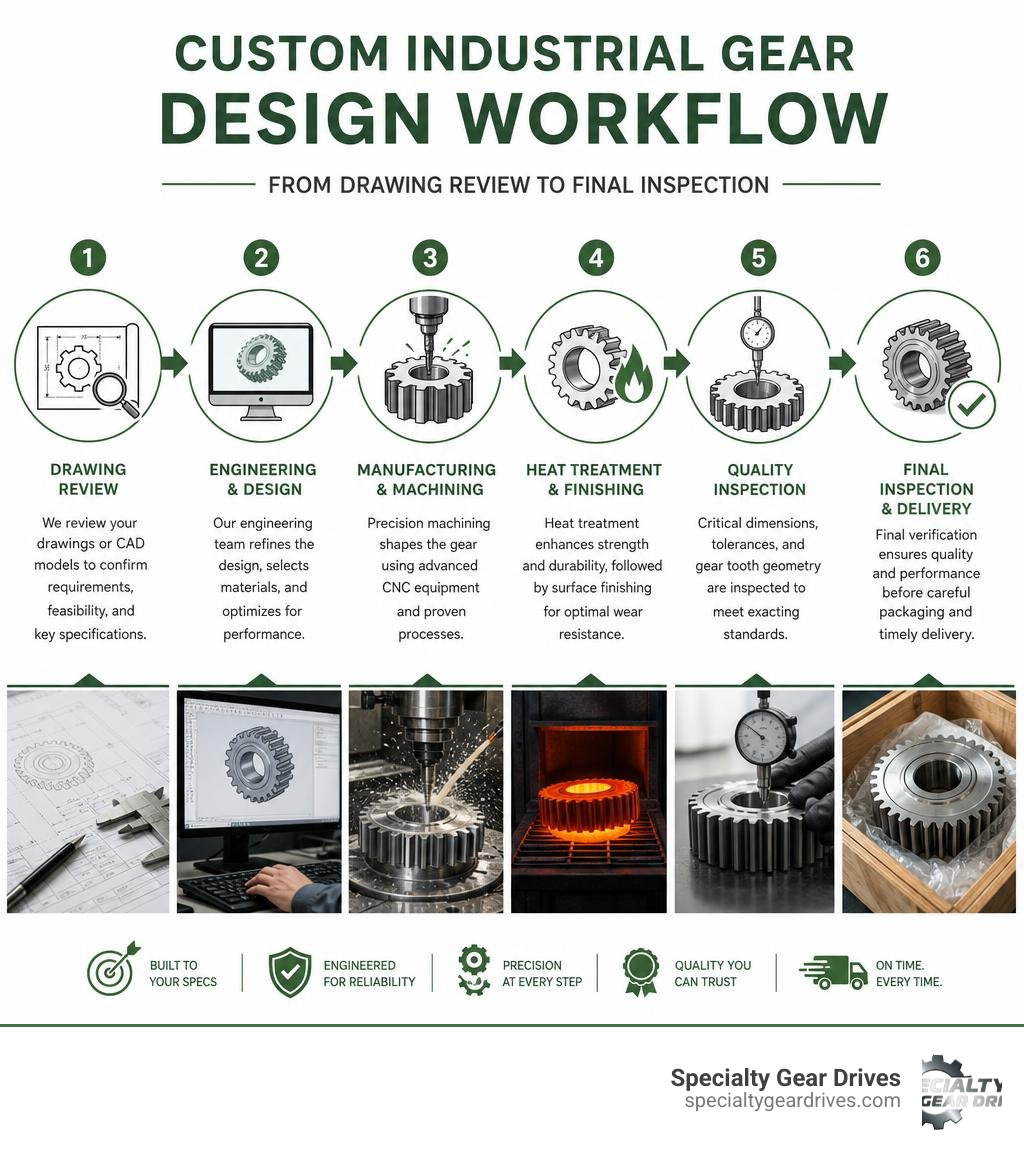
Manufacturing custom industrial gears requires specialized machine tools and highly controlled processes to turn raw forgings into finished components. Precision levels are measured using international standards like AGMA, ISO 1328, and DIN.

The manufacturing sequence begins with gear blank preparation, which involves turning and boring on CNC lathes to establish precise concentricity. Next, gear hobbing uses a rotating cutting tool called a hob to progressively generate the teeth on spur, helical, and worm gears. For internal gears or spaces where a hob cannot clear, gear shaping uses a reciprocating cutter to carve out the teeth. Broaching is used to cut internal keyways and splines rapidly by pulling a multi-toothed cutting tool through the bore.
To verify that these processes meet your exact specifications, quality control teams use coordinate measuring machines (CMMs). These automated inspection systems measure tooth profiles, lead errors, and pitch variations down to the micron.
Manufacturing Tolerances and Micro-Geometry in Custom Industrial Gears
High-performance gearboxes require micron-level accuracy to minimize noise and maximize power transmission efficiency. This level of precision is achieved through profile grinding after the gear has undergone heat treatment.
Profile grinding removes the minor dimensional distortions caused by the heating and quenching processes. This step refines the surface finish to a roughness value of Ra < 0.4 μm.
Refined surface finishes and precise backlash control prevent the teeth from binding while allowing sufficient space for lubricating oil films. By optimizing the micro-geometry of the tooth profile, engineers can ensure even load distribution across the entire tooth face, preventing localized stress concentrations that lead to premature tooth pitting or breakage.
Engineering Considerations for Custom Industrial Gears Design
Designing a custom gear requires a thorough evaluation of the operating environment and the mechanical loads the gear will experience. A gear designed solely for torque transmission may fail prematurely if it cannot handle the ambient conditions of your plant.
Engineers must calculate the continuous torque load, peak shock loads, and rotational speed to establish the necessary tooth size and face width. The duty cycle, which is the number of hours the machine runs per day, determines the required fatigue life of the metal.
Environmental factors are equally critical. High-humidity environments, like those found in Florida and Georgia processing plants, require specialized lubricants and corrosion-resistant materials to prevent rust.
When original equipment manufacturer (OEM) drawings are unavailable, reverse engineering is used to recreate obsolete components. This process involves measuring a worn sample gear, calculating its original geometry, and creating new CAD models that often exceed the performance of the original part.
If your entire drive system is showing signs of wear, you can read The Ultimate Guide to Gearbox Rebuild for a complete breakdown of the restoration process.

Frequently Asked Questions about Custom Industrial Gears
What are the typical lead times and MOQs for custom industrial gears?
Lead times for custom gears generally range from 2 to 6 weeks, depending on the complexity of the gear geometry, material availability, and the required heat treatment. Simple spur gears made from stock materials can often be completed in under 2 weeks, while complex spiral bevel sets requiring carburizing and profile grinding may take up to 6 weeks.
Minimum order quantities (MOQs) are highly flexible. Custom manufacturers can produce a single prototype or replacement gear for an emergency repair, as well as production runs of 50 to 100 pieces for equipment manufacturers.
How do custom gears compare to standard off-the-shelf gears in cost and performance?
Custom gears have a higher upfront design and manufacturing cost than standard catalog gears. However, they deliver significant long-term savings by reducing maintenance costs, vibration, and unplanned downtime.
Standard gears often force you to compromise on shaft spacing, materials, or tooth geometry, which leads to faster wear and lower efficiency. Custom gears are engineered to fit your exact operational parameters, often extending the overall service life of your machinery.
Why do heavy industries in the Southeast require custom gear solutions?
Southeast manufacturing plants operate in some of the most challenging environmental conditions in the country. High humidity, coastal salt air, and elevated ambient temperatures accelerate gear wear, oil breakdown, and housing corrosion.
Pulp and paper mills, petrochemical plants, and phosphate mines in this region require custom gears with specialized alloy compositions, precise surface finishes, and robust heat treatments to withstand these harsh conditions.
If you suspect your Florida facility has a failing gearbox, you can learn about the warning signs in our article on Industrial Gearbox Repair Florida 7 Signs You Need a Pro.
Conclusion
Sourcing the right custom industrial gears is essential for keeping your heavy machinery running efficiently and preventing costly production stoppages. From selecting the proper gear geometry to choosing the right alloy steel and heat treatment, every decision impacts the reliability and service life of your drive systems.
At Specialty Gear Drives, based in Largo, Florida, we specialize in custom gear manufacturing and comprehensive industrial gearbox repair. We serve heavy industries across Florida, Georgia, Alabama, South Carolina, Mississippi, and Louisiana, including pulp and paper mills, mining operations, and petrochemical plants.
Our services include:
- 24-48 hour emergency service to get your critical machinery back online quickly
- Free pickup and delivery across our Southeast service area
- Up to 60% savings compared to the cost of purchasing a brand-new OEM gearbox
- A 24-month warranty on all of our rebuild and manufacturing work
If you need a replacement gear manufactured to print, or if you need to reverse-engineer an obsolete component, contact us today. To learn more about our repair and manufacturing capabilities, visit the Specialty Gear Drives Industrial Gearbox Repair page to request a quote.