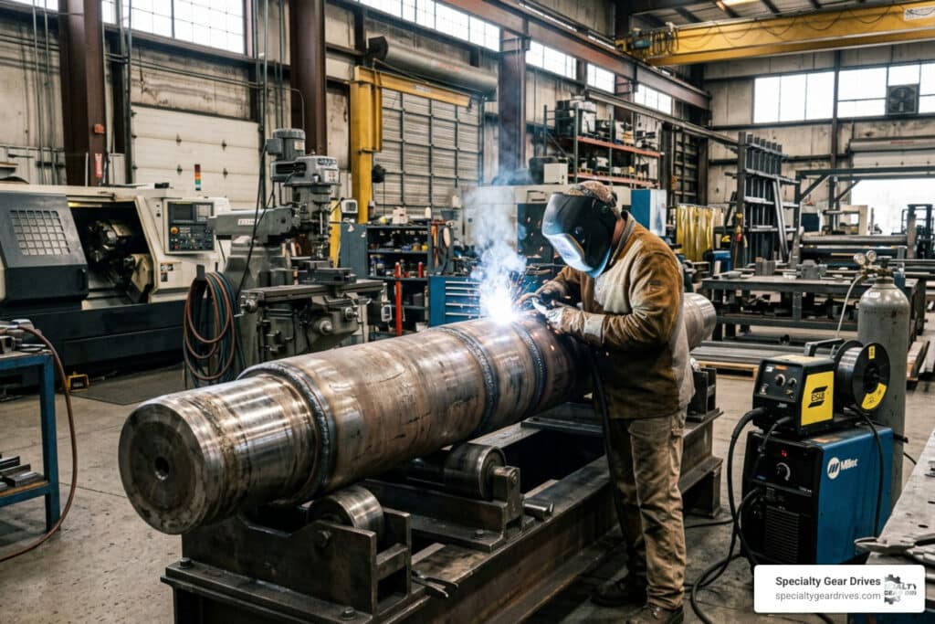
Shaft repair welding is the process of using fusion welding or thermal deposition techniques to restore a worn, cracked, or damaged shaft to its original dimensions and mechanical properties — so it can go back into service without the cost or lead time of a full replacement.
If you need a quick answer on how it works, here’s the short version:
How Shaft Repair Welding Works (Quick Reference)
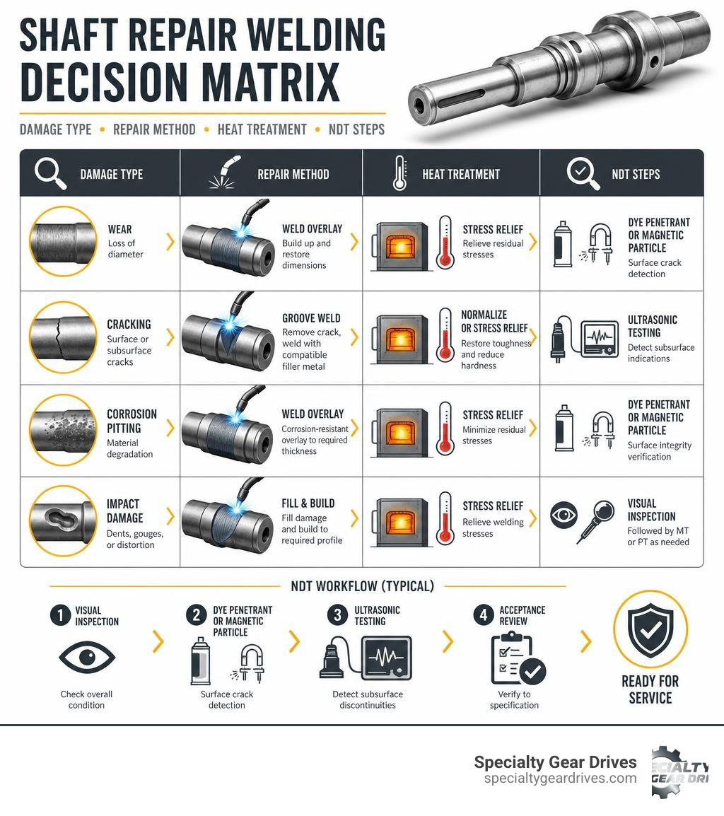
- Identify the damage – Determine cause (wear, corrosion, cracking) and shaft material
- Prepare the surface – Machine away damaged material, clean thoroughly, inspect for cracks
- Preheat the shaft – Typically 400-500°F for medium-carbon steels like AISI 1045 or 4140
- Apply weld overlay or structural weld – Using MIG, TIG, submerged arc, or other processes
- Control heat input – Rotate shaft during welding, monitor interpass temperature
- Post-weld heat treatment – Stress relief at ~1100°F to prevent brittle martensite
- Machine back to spec – Turn and grind to final dimensions
- Inspect and verify – Dye penetrant, magnetic particle, or ultrasonic testing
For a plant manager, a failed shaft isn’t just a mechanical problem — it’s a production stoppage. Shafts are among the most commonly weld-repaired components in industrial machinery, and for good reason. Rotors and shafts valued anywhere from $20,000 to nearly a million dollars are routinely brought back to life through welding rather than replaced.
But a repair done wrong can be worse than no repair at all. Fatigue is the leading cause of shaft failures — and improper weld repairs are a well-documented trigger for exactly that kind of fatigue cracking. The weld itself isn’t always the problem. It’s the metallurgical changes, residual stresses, and stress concentrations that come with it when the procedure isn’t right.
This guide walks you through how to do it correctly.
Common Causes of Shaft Damage and Failure
Before we strike an arc, we have to understand what went wrong. A shaft operating in an industrial environment is subjected to a complex cocktail of mechanical loads, environmental attacks, and operational stresses. Simply building up the worn area without diagnosing the root cause is a recipe for a repeat failure.
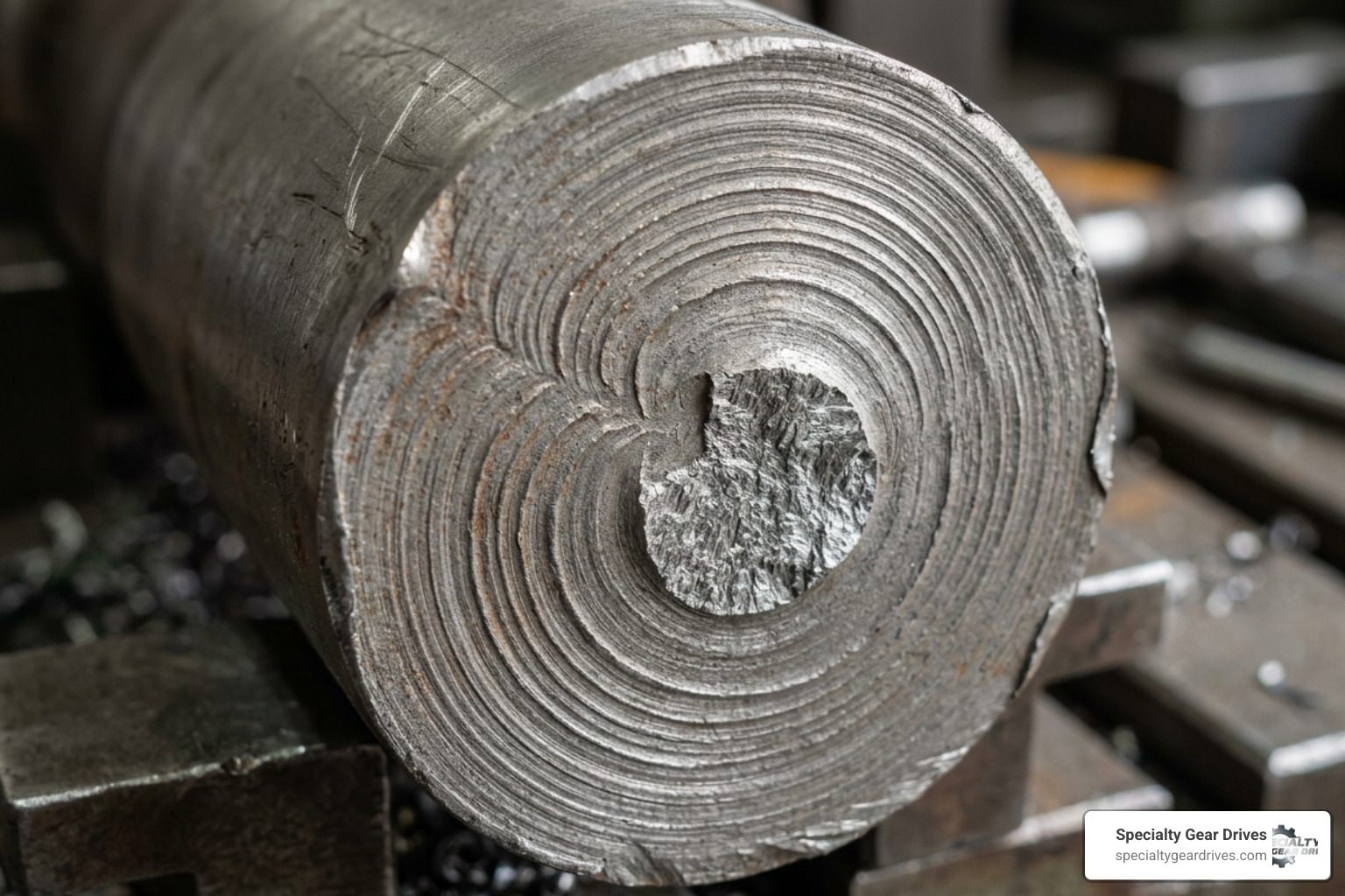
- Fatigue: This is the single biggest culprit behind industrial shaft failures. Rotating shafts experience cyclic loading, meaning they bend slightly with every single rotation. Over millions of cycles, tiny microscopic cracks can form, often starting at stress raisers like keyways, sharp shoulders, or weld defects. Eventually, these cracks propagate until the shaft snaps.
- Abrasive Wear: This occurs when hard foreign particles—such as dirt, metal chips, or process debris—get trapped between the shaft and a seal or bearing, grinding away the metal surface over time.
- Adhesive Wear (Galling): When two metallic surfaces slide against each other under high pressure without adequate lubrication, they can microscopically weld together and tear apart. This leaves a torn, highly damaged surface.
- Corrosion: Chemical attack from moisture, acids, or process chemicals eats away at the shaft material. Pitting corrosion is especially dangerous because each tiny pit acts as a geometric stress concentrator where a fatigue crack can start.
- Fretting: This is a specialized form of wear that occurs at the contact interface between tightly fitted components (like a bearing inner ring on a shaft journal) subjected to minute, oscillatory vibrations. It leaves a characteristic rusty-looking powder and fine pitting.
Pre-Weld Considerations and Material Identification
Attempting to weld a shaft without knowing its chemical composition is a gamble with incredibly high stakes. Different steels behave in wildly different ways when heated and cooled.
First, we must identify the base material. Is it low-carbon steel, medium-carbon steel (like AISI 1045), or an alloy steel (like AISI 4140)? Low-carbon steels are highly weldable and rarely crack. However, most industrial shafts are medium-carbon or alloy steels because they need higher strength and toughness.
AISI 1045 is extremely common for general shafting, but its carbon content (0.43–0.50%) makes it highly susceptible to forming brittle martensite in the heat-affected zone (HAZ) if it cools too quickly. For more details on this specific challenge, you can read the Latest guidelines on welding 1045 steel.
To identify the material in a repair shop setting, we use several diagnostic tools:
- Spark Testing: Grinding a small, non-critical area of the shaft and observing the color, length, and shape of the spark stream. High-carbon steels produce bright, exploding bursts, while alloy steels like 4140 produce distinct reddish-orange carrier lines.
- Hardness Survey: Using a portable hardness tester to check the hardness of the core and the surface. A highly hardened surface might indicate induction hardening or carburizing, which requires special tempering consideration before welding.
- Chemical Analysis: When dealing with critical, high-value rotors, we use portable X-ray fluorescence (XRF) or optical emission spectrometry (OES) to get an exact elemental breakdown.
We also calculate the Carbon Equivalent (CE) of the steel. The higher the carbon equivalent, the higher the risk of cold cracking (hydrogen-induced cracking), and the more critical preheating and post-weld heat treatment become.
Primary Processes for Shaft Repair Welding
Choosing the right welding process depends on the shaft material, the extent of the damage, the required build-up thickness, and the balance between cost and quality.
- Gas Metal Arc Welding (GMAW / MIG): Excellent for rapid material buildup on larger shafts. When set up with a rotating positioner, MIG welding can deposit large amounts of filler metal quickly. We typically use a spray transfer mode or flux-cored wire to ensure deep penetration and low porosity.
- Gas Tungsten Arc Welding (GTAW / TIG): The gold standard for precision. TIG welding offers absolute control over the weld pool and heat input, making it ideal for smaller shafts, keyway repairs, and stainless steel applications. It produces exceptionally clean welds with no slag, though it is much slower than MIG.
- Submerged Arc Welding (SAW): For massive industrial shafts and heavy rotors, SAW is the preferred industrial method. It uses a continuously fed consumable electrode under a blanket of fusible flux. It yields incredibly high deposition rates and superb weld quality with minimal distortion, but requires specialized, heavy equipment.
- Directed Energy Deposition (DED): This is a modern additive manufacturing process that uses a laser or electron beam to melt metal powder or wire as it is deposited. It creates an incredibly small heat-affected zone and minimizes thermal deformation, making it highly attractive for high-precision repairs. For a deeper look at this technology, see the Research on Directed Energy Deposition for shaft repair.
| Welding Process | Deposition Rate | Heat Input / Thermal Impact | Equipment & Setup Cost | Best Suited For |
|---|---|---|---|---|
| TIG (GTAW) | Low | Medium (Highly localized) | Moderate | Small shafts, stainless steel, keyways |
| MIG (GMAW) | Medium-High | Medium-High | Low-Moderate | General carbon steel shaft buildup |
| Submerged Arc | Very High | High (but uniform) | High | Large diameter heavy industrial rotors |
| DED (Laser) | Moderate | Very Low | Extremely High | High-precision, low-distortion alloy repairs |
How Location Influences Shaft Repair Welding
Where the damage is located on the shaft dictates how we approach the repair:
- Bearing Journal: Bearing fits have incredibly tight dimensional tolerances. The primary challenge here is preventing distortion that would ruin the shaft’s concentricity. Thermal spray or a highly controlled TIG overlay are often preferred here to keep heat input to an absolute minimum.
- Keyways: Worn or stripped keyways are common. If we are welding inside a keyway, we must be careful not to create stress concentration zones. Often, the best practice is to weld the old keyway completely shut, machine the shaft back to a round profile, and mill a brand new keyway 90 or 180 degrees offset from the original location.
- Mid-Shaft: Damage in the middle of a shaft is highly susceptible to bending stresses. Any weld repair here must be structural, ensuring complete fusion and zero internal defects like slag inclusions or porosity, which would act as initiation points for bending fatigue.
- Diameter Transitions: The shoulders where a shaft steps down in size are natural stress raisers. We must never terminate a weld overlay right at a diameter transition. The weld runout should always extend well past the shoulder onto the larger diameter, and then be machined back to create a smooth, generous radius that distributes mechanical stress.
Post-Weld Heat Treatment in Shaft Repair Welding
When we weld on medium-carbon or alloy steels, the rapid cooling of the weld pool acts like a quench. This rapid cooling transforms the microstructure in the heat-affected zone into martensite—an incredibly hard, brittle structure that is highly prone to cracking under load.
To prevent this, Post-Weld Heat Treatment (PWHT) is essential.
For standard carbon steels like 1045, we perform stress relief by heating the welded area uniformly to approximately 1100°F (593°C) and holding it for one hour per inch of shaft diameter. This allows the atoms in the stressed crystal lattice to rearrange, tempering the brittle martensite back into a tough, ductile structure.
Once the holding time is complete, the shaft must be cooled slowly. We wrap the weldment in heavy ceramic fiber blankets, dry sand, or vermiculite to slow the cooling rate down to a crawl. This slow cooling prevents residual stresses from locking back into the metal.
Can PWHT ever be avoided? Only under very specific circumstances. If the shaft is made of low-carbon, highly ductile steel (like AISI 1018 or 1020) and is not subjected to high cyclic fatigue or heavy radial loads, you may get away with slow cooling alone. However, for any critical rotating equipment, skipping stress relief is a massive gamble.
Step-by-Step Best Practices to Minimize Distortion
Distortion is the enemy of rotating shafts. If a shaft warps even a fraction of a millimeter during welding, it will vibrate violently in service, destroying bearings and seals in short order. Here is how we prevent it:
- Preheating: We preheat the entire weld zone uniformly to 400–500°F (204–260°C) before striking an arc. Preheating reduces the thermal gradient between the weld pool and the cold base metal, slowing down the cooling rate and preventing localized shrinkage that pulls the shaft out of alignment.
- Shaft Rotation: We never weld a long linear bead down one side of a shaft. This uneven heat input causes the shaft to bow. Instead, we mount the shaft on a rotary positioner and weld circumferentially.
- Lateral (Circumferential) Welding: Welding around the circumference distributes the heat evenly. For manual repairs, we use a balanced sequence—welding a short bead, rotating the shaft 180 degrees to weld the opposite side, and repeating.
- Interpass Temperature Control: We monitor the temperature of the shaft between weld passes using tempilstiks or an infrared thermometer. For stainless steel, we keep the interpass temperature below 300°F to preserve corrosion resistance. For carbon steels, we maintain our preheat temperature but avoid letting the shaft get excessively hot, which can lead to grain growth and loss of toughness.
For practical hands-on insights on managing these parameters during manual repairs, you can review these Practical tips for TIG overlay on stainless steel.
Quality Verification and Non-Destructive Testing (NDT)
A weld repair is only as good as its verification. We use a rigorous multi-step inspection process to ensure the integrity of our repairs:
- Visual Inspection (VT): Checking for surface defects like undercut, overlap, or visible porosity immediately after welding.
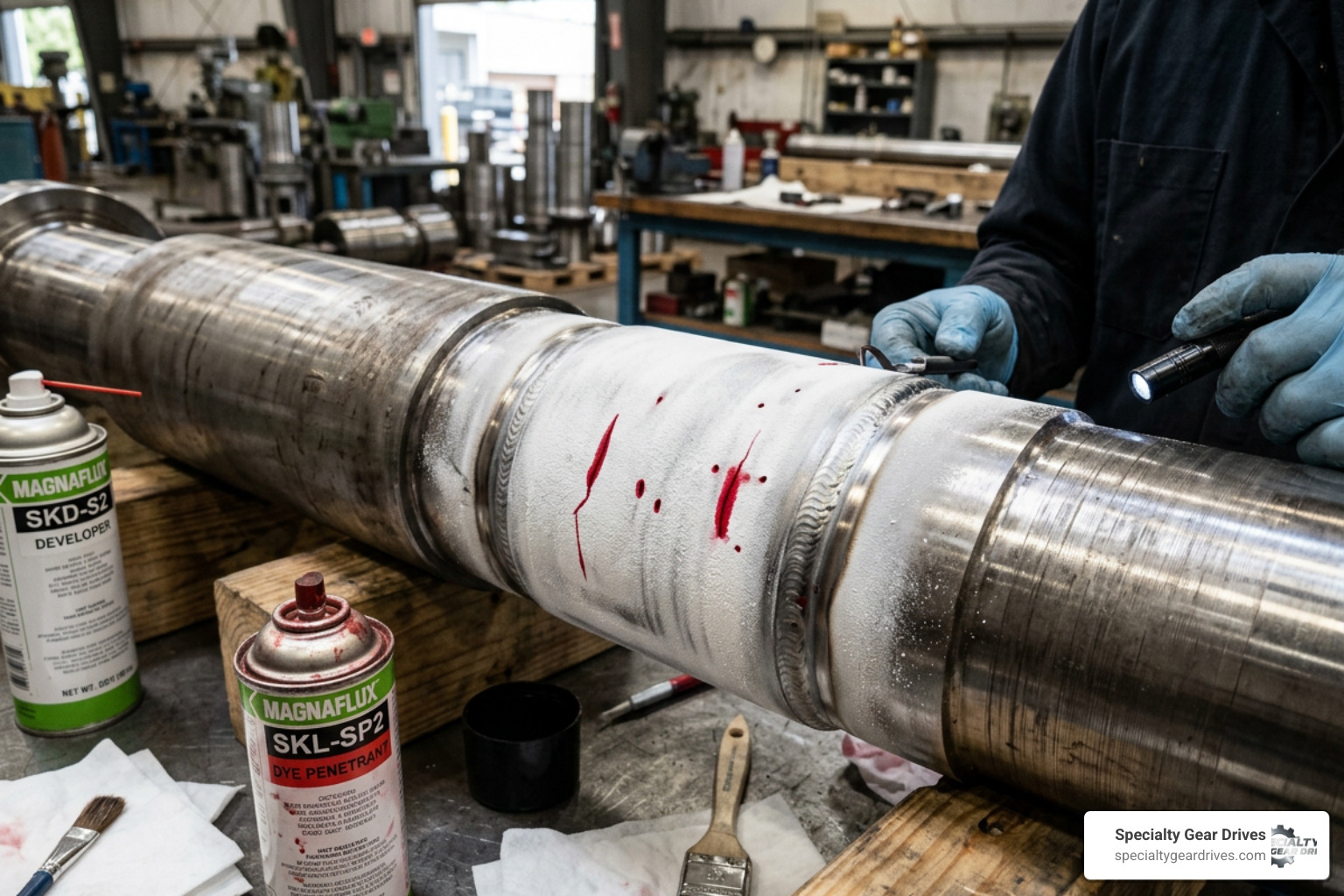
- Liquid Dye Penetrant Testing (PT): We apply a highly visible red dye to the machined surface, wipe away the excess, and apply a white developer. Any subsurface cracks or pinholes will draw the dye out, making them highly visible. We perform PT both after undercutting the initial damage (to ensure we got all the old cracks out) and after final machining.
- Magnetic Particle Testing (MT): For ferromagnetic steels, MT is highly effective at finding surface and near-surface discontinuities by detecting disruptions in a magnetic field applied to the shaft.
- Ultrasonic Testing (UT): For critical structural welds, we use high-frequency sound waves to scan the entire volume of the weld, ensuring there is complete fusion at the root and zero internal voids.
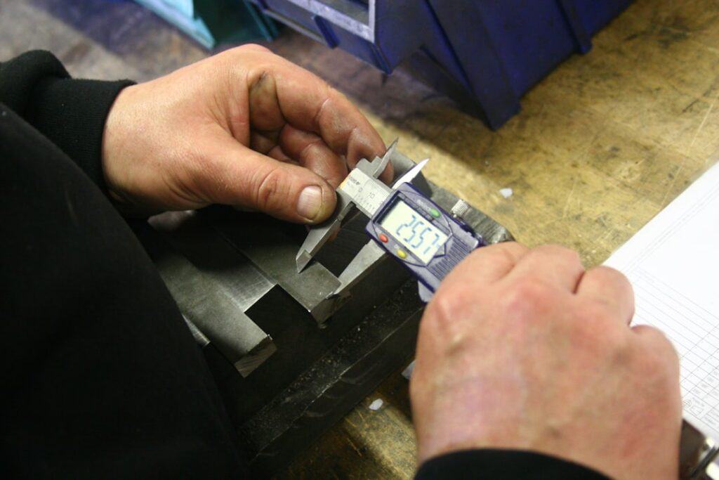
- Runout and Concentricity Checks: After machining, we mount the shaft on centers or V-blocks and use dial indicators to check the runout along the entire length of the shaft. Our target runout is typically under 0.001 inches (0.025 mm) to ensure smooth, vibration-free operation.
Alternative Repair Methods vs. Fusion Welding
While welding is incredibly versatile, it is not always the best tool for the job. We must weigh it against other common repair methods:
- Thermal Spraying (Metalizing): This process sprays molten metal droplets onto a grit-blasted shaft surface. It creates a mechanical bond rather than a metallurgical fusion bond. The massive benefit is that the substrate temperature stays below 250°F, meaning zero risk of thermal distortion or HAZ cracking. However, because it is only a mechanical bond, it cannot handle high impact, heavy radial loads, or flexing.
- Brush Plating: An electrochemical process that deposits metals like nickel or hard chrome directly onto the worn area. It creates an exceptionally strong molecular bond with zero heat input. It is fantastic for restoring worn bearing journals with minor wear (under 0.010 inches), but is slow and expensive for thick build-ups.
- Sleeving: Machining the worn area down, heating a precision-ground metal sleeve, and shrink-fitting it over the shaft. This is a very reliable, heat-free repair for seal journals, but it reduces the solid cross-sectional area of the shaft, which can lower its torque capacity.
- Metal-Filled Epoxies (Polymer Putties): Cold-applied composite materials. While highly useful for emergency, low-load, or non-rotating applications, they do not have the shear strength or temperature resistance required for heavy-duty industrial power transmission.
For complex assemblies like gearboxes, selecting the right approach is vital. You can find More details on industrial gearbox repair to see how shaft restoration fits into a complete machine rebuild.
Frequently Asked Questions about Shaft Repair
Can post-weld heat treatment (PWHT) be avoided during shaft repair?
Generally, no—not if the shaft is made of medium-carbon or alloy steel and operates under cyclic loads. Skipping PWHT leaves high residual tensile stresses and a brittle heat-affected zone, which dramatically accelerates fatigue cracking. It can only be avoided on low-carbon steels (under 0.25% carbon) or in non-critical, low-stress applications where slow, insulated cooling is sufficient to prevent cracking.
What are the risks of improperly executed shaft weld repairs?
The primary risk is catastrophic structural failure. If a weld has incomplete fusion, hydrogen embrittlement, or terminates at a sharp shoulder, it will act as a major stress raiser. Under normal operating rotation, bending fatigue will initiate at these defects, leading to sudden, unexpected shaft breakage. This can destroy the surrounding gearbox, damage coupled machinery, and present serious safety hazards.
What industry standards govern rotating shaft repairs?
While there is no single, all-encompassing code dedicated solely to shaft welding, several standards provide excellent framework guidelines. The American Welding Society publishes AWS D14.6 (Specification for Welded Joints in Machinery and Equipment), which covers rotating equipment. Additionally, ANSI/EASA AR100 provides best practices for the repair of rotating electrical machinery, including detailed limits on shaft runout and repair methodologies.
Conclusion
Shaft repair welding is a highly technical blend of metallurgy, welding engineering, and precision machining. When executed with the proper preheat, correct filler metals, controlled heat input, and thorough post-weld stress relief, a repaired shaft can deliver a service life that matches or even exceeds a brand-new replacement—at a fraction of the cost and lead time.
At Specialty Gear Drives, we understand that when your industrial machinery goes down, time is money. Based in Largo, Florida, we specialize in repairing and rebuilding industrial gearboxes for heavy industries like plastics, food processing, and pulp/paper. We offer a rapid 24–48 hour emergency service, free pickup and delivery, and up to 60% savings compared to buying new—all backed by our industry-leading 24-month warranty.
Don’t let a worn shaft halt your production. Contact Specialty Gear Drives for expert shaft and gearbox repair today, and let our team of specialists bring your critical rotating equipment back to peak operating condition.